
Manual
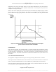
Table Of Contents
- ANSI C63.17-2006 Front Cover
- Title page
- Introduction
- Notice to users
- Participants
- Contents
- American National Standard Methods of Measurement of the Electromagnetic and Operational Compatibility of Unlicensed Personal Communications Services (UPCS) Devices
- 1. Overview
- 2. Normative references
- 3. Definitions, symbols, acronyms, and abbreviations
- 4. Radiated and conducted emissions test methodology
- 4.1 Test facilities and equipment
- 4.2 Test configurations and setup
- 4.3 Transmitted power and monitoring threshold limits
- 4.4 Limits for radiated and conducted tests
- 4.5 Conducted measurements of products with identical collocated transmitting and monitoring antennas
- 4.6 Conducted measurements of products with collocated transmitting and monitoring antennas of different types
- 4.7 Conducted measurements of products with arbitrarily placed transmitting and monitoring antennas
- 4.8 Radiated measurements of products with identical collocated transmitting and monitoring antennas
- 4.9 Radiated measurements of products with collocated transmitting and monitoring antennas of different types
- 4.10 Radiated measurements of products with arbitrarily placed transmitting and monitoring antennas
- 4.11 Manufacturer’s declarations and descriptions
- 5. Measurement instrumentation
- 6. RF measurements
- 7. Monitoring tests
- 8. Time and spectrum window access procedure
- 9. Test report
- 9.1 Test report contents
- 9.2 Applicable standards
- 9.3 Equipment units tested
- 9.4 Test configuration
- 9.5 List of test equipment
- 9.6 Units of measurement
- 9.7 Location of test site
- 9.8 Measurement procedures
- 9.9 Reporting measurement data
- 9.10 General and special conditions
- 9.11 Summary of results
- 9.12 Required signatures
- 9.13 Test report appendixes
- 9.14 Test report disposition
- Annex A (informative) 47CFR15, Subpart D—Rules and test cases for UPCS devices
- Annex B (informative) Radiated and conducted measurement of power output and monitoring thresholds
- Annex C (informative) Options for implementing the tests of Clause 7 and Clause 8
ANSI C63.17-2006
Methods of Measurement of the Electromagnetic and Operational Compatibility of UPCS Devices
The equivalent coverage test for the transmitting and monitoring antennas is then performed as follows:
a) Set up the reference antenna with controlled polarization and with its major lobe facing the
EUT’s direction of maximum transmit radiation, at a distance r (meeting the far-field
conditions) from the EUT antennas. Apply a signal on the appropriate channel at power P
Tref
(see definitions) to the reference antenna terminals to create the deferral test signal of Clause 7
at the desired level at the transmit antenna.
b) Test to see that the EUT defers with vertical reference antenna polarization.
c) Repeat the test with horizontal polarization for the reference antenna.
The EUT shall defer for one or the other of the two orthogonal reference antenna polarizations. Otherwise,
it fails the equivalent coverage test.
4.7
4.8
Conducted measurements of products with arbitrarily placed transmitting and
monitoring antennas
The transmit power compliance test of Clause 6 shall be performed as stated in 4.5. Calculate the maximum
appropriate threshold T
L
or T
U
using Equation (2) or Equation (3) and verify that the EUT transmits when
interference power sufficiently less than T
L
or T
U
is applied to the monitoring antenna terminals and defers
when interference power equal to or greater than T
L
or T
U
is applied to the terminals.
The equivalent coverage test for the transmitting and monitoring antennas is then performed as follows:
a) Set up
the reference antenna with vertical polarization and with its major lobe facing the EUT at
a distance r (meeting the far-field conditions) from the EUT transmit antenna in the direction of
the EUT’s maximum radiation.
b) Apply power to the reference antenna terminals and adjust it to the level P
Tref
.
c) Move the reference antenna (without changing its orientation) in the direction of the EUT’s
maximum radiation to a distance r + s from the monitoring antenna, where s is the maximum
possible distance between the transmit and monitoring antennas, as specified by the EUT
manufacturer.
d) Align the EUT monitoring antenna such that the direction of its minimum sensitivity faces the
reference antenna.
e) Apply power P
Tref
to the reference antenna and illuminate the EUT monitoring antenna.
f) Repeat step e) with the reference antenna horizontally polarized.
The EUT shall defer with one or the other of two orthogonal polarizations of the reference antenna, or the
EUT fails the equivalent coverage test.
Radiated measurements of products with identical collocated transmitting and
monitoring antennas
Set up the EUT and reference antenna with its major lobe facing the EUT in the far field with separation r
in meters. Initiate EUT transmission and find the direction of the EUT’s maximum radiation. Measure the
EUT EIRP. EIRP
EUT
(dBm) can be calculated from the measured radiated field intensity in the direction of
maximum radiation E
EUTmax
using the following equation:
8.104log20=EIRP
EUTmaxEUT
−
+
rE
(7)
12
Copyright © 2007 IEEE. All rights reserved.
Licensed to Sid Sanders. ANSI order X_30788. Downloaded 11/19/2007 2:45 PM. Single user license only. Copying and networking prohibited.