
User's Manual


114
SMCD3GNV4 and SMCD3GNV4E Wireless EMTA Gateway Administrator Manual
2. Measure the gap between holes with a ruler. Dimensionally confirm the template by measuring each
value for accuracy before drilling holes.
3. Use a center punch to mark the center of the holes.
4. Locate the marks on the wall for the mounting holes.
5. Drill holes to a depth and diameter appropriate for the size and type of hardware you have selected.
6. If necessary, install an anchor in each hole. Use M3.5 x 40 mm screws with a flat underside and
maximum screw head diameter of 6.5 mm (0.25 inches) to mount the Gateway.
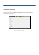
7. Using a screwdriver, turn each screw until the head protrudes from the wall. The figure below is an
example for mounting Gateway on a concrete surface. Leave at least 2.5 mm (0.10 inches) between
the wall and the underside of the screw head. The maximum distance from the wall to the top of the
screw head is 5.0 mm (0.20 inches).
8. Place the Gateway so the keyholes are above the mounting screws.
9. Slide the Gateway down so it stops against the top of the keyhole opening.
10. Reconnect the coaxial cable and Ethernet cables. Reconnect the power cord to the Gateway and the
electrical outlet.