USER’S MANUAL IEEE802.
Foreword Explanation of the signals In order to let you set up and use this product correctly, please pay attention when reading or browsing the manual as you see these signals listed below. Warning/ Danger Users should read the explanation carefully and understand it completely, otherwise users might be in danger or even be injured. Caution/ Be Careful Remind users to be careful when setting up the product and to avoid damaging the product or its system programs.
Trademarks: All trade names and trademarks are the properties of their respective companies. Copyright © 2006, All Rights Reserved.
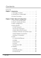
Contents Foreword Chapter 1 Introduction . . . . . . . . . . . . . . . . . . . . . . . . . . . . . 1 1. Package Contents . . . . . . . . . . . . . . . . . . . . 1 2. Introduction to BLW-54MF . . . . . . . . . . . . . . . 2 3. Product Housing. . . . . . . . . . . . . . . . . . . . . . . 4 Chapter 2 Basic Setup & Configuration . . . . . . . . . . . . . . . 7 1. How to Set Up BLW-54MF . . . . . . . . . . . . . . . 7 2. Client’s Computer Setup . . . . . . . . . . . . . . . . 8 3. :HE &RQÀJXUDWLRQ . . . . . . .
7. Status . . . . . . . . . . . . . . . . . . . . . . . . . . . . . . . . 41 7.1 Device Information . . . . . . . . . . . . . . . . . 41 7.2 Log. . . . . . . . . . . . . . . . . . . . . . . . . . . . . . . 42 7.3 Log Setting . . . . . . . . . . . . . . . . . . . . . . . . 43 7.4 Statistics. . . . . . . . . . . . . . . . . . . . . . . . . . . 44 7.5 Wireless . . . . . . . . . . . . . . . . . . . . . . . . . . . 44 Chapter 3 Advanced Setup & Configuration . . . . . . . . . . 45 1. Routing . . . . . . . . . .
1 1 Introduction 1. Package Contents After purchasing BLW-54MF Wireless Router form a distributor or an agency, please open the package and check that all the components listed below are included. If there is any item missing or damaged, please contact with the distributor or the agency at once.
1 2. Introduction to BLW-54MF Thank you for purchasing BLW-54MF IEEE802.11g Wireless Multifunction Broadband Router. This 802.11b/g wireless router is a multifunction device which provides (1) shared broadband Internet access for LAN users through 4-port switching hub, (2) WDS Bridge/Repeater function, and (3) unique EZ-GO function. Moreover, it has an external switch to switch between AP and Router function that makes BLW-54MF an easy-to-use broadband router.
1 œSupport Wireless Authentication BLW-54MF supports 64/128 Bit WEP, WPA, WPA AUTO, WPA-PSK/ EAP and WPA2-PSK/EAP which can prevent others from stealing your bandwidth and avoid information leak. œSupport Anti-DoS Function SPI Anti-DoS Firewall can prevent hacker's invasion. œSupport Virtual Server & DMZ Virtual server and DMZ functions can let BLW-54MF access LAN service through Internet.
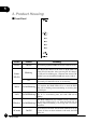
1 3. Product Housing ŜFront Panel LEDs Status Meaning Power On/Off When starting up BLW-54MF, the Power LED will be on. Blinking Press the EZ-GO button at the back of BLW-54MF and enable EZ-GO function. After pressing EZ-GO button, the LED will be blinking for 5 minutes that means GWUS54SG can search for BLW-54MF and connect with it. Status EZ-GO If BLW-54MF has connected with GW-US54SG successfully, EZ-GO LED will be on all the time.
1 ŜRear Panel Ports Function AC Plug the power cord into this port and the other side of the adaptor should be plugged into the socket. WAN Connect a DSL or Cable Modem to the WAN port and link to the internet. If your modem came with a cable, use the supplied cable. Otherwise, use a standard cable. LAN Use standard LAN cables (RJ45 connectors) to connect your PCs to these ports. Any LAN port can be connected with another hub, if required.
2 2 Basic Setup & Configuration 1. Hardware Installation 1.Unwrap the package of BLW-54MF Wireless Router and check if the components are complete with nothing missing. 2.Choose a Proper Installation Site. Select a suitable place on the network to install BLW-54MF Wireless Router. And make sure that the wireless router and the DSL/Cable modem are not powered on yet.
2 3.Connect LAN Cables. Use standard LAN cables (RJ-45) to connect PCs to the switching hub ports on BLW-54MF. Both 10 Base-T and 100 Base-T connections can be used simultaneously. 4.Connect WAN Cable. Connect the DSL or Cable modem to the WAN port on BLW-54MF. 5.Power On. Power the DSL or Cable modem on. At last, connect the adapter with BLW-54MF and plug the other side of the power cord into the power socket. Power BLW-54MF Wireless Router on.
2.ņMS-DOSŇwindow will appear. 3.TypeņipconfigŇafter the command ofņc:>Ňand then press enter. 2 4.MS-DOS will appear your NIC address in the window, please take notice of the value ofņIP AddressŇandņDefault Gateway.Ň 5.The value ofņDefault GatewayŇis the IP address of BLW-54MF. œWindows2000/XP 1.Please make sure that you do have the authority to access as an ņAdministratorŇor you are already one of theņSystem Administrators.Ň 2.
2 3. Web Configuration To establish a connection between your PC and the BLW-54MF Wireless Router: 1.Star the web browser. In the Address box, enterņhttp://192.168.1.1Ň which is the default IP Address of the BLW-54MF Wireless Router. Press ņEnterŇon your keyboard, and the pop-up will ask you to enter the User Name and Password to get into the program. 2.Enter the default User NameņadminŇand PasswordņadminŇ(casesensitive) and then clickņOKŇto enter the system.
3.After entering the system, BLW-54MF will show you the Main page. During configuration, you can use the tabs on the top of the page and 2 menu at the left side of the page to navigate. Besides, it is necessary that, after configuring, you should clickņApplyŇto enable the settings you have made. If your BLW-54MF Wireless Router does not response, and you cannot enter the web configuration page, please follow the steps below to check if there is any problem: 1.
3.You have to make sure that your PC and BLW-54MF are on the same segment. Besides, you have to use the wired LAN interface 2 when first accessing the web configuration page, the wireless interface only works when the settings of BLW-54MF matches your PC's wireless settings. 4. Setup Wizard After logging in the configuration page, aņSetup WizardŇdialog box pops up. You may choose to use setup wizard to set up BLW-54MF or use configuration page to set up all the settings.
4.1 Set Password 2 Step 1ĈThe default User Name of BLW-54MF Wireless Router isņ adminŇand Password isņadmin.ŇIt is recommended that you should change the default password to have better protection over the router and the LAN. You must memorize the password set by you to enter the system; otherwise, you have to restore the whole systems and then configure the settings again. Please enter your new password twice on the following page and then clickņNextŇto keep on setting up. 4.
2 4.3 Set LAN & DHCP Server Step 3ĈYou can do LAN port configuration and enable/disable DHCP server through this page. œLAN IP AddressĈHere is the IP address of the LAN side of BLW54MF. The default IP address isņ192.168.1.1Ň. œLAN Subnet MaskĈThe Subnet Mask of the LAN side of BLW-54MF isņ255.255.255.0Ň. œDHCP ServerĈDHCP stands for Dynamic Host Control Protocol.
4.4 Select Internet Connection Type 2 Step 4ĈThe followings are the most common used connection types: Obtain IP automatically (DHCP client), Fixed IP address, and PPPoE. If you want to know more about the other types of WAN configurations, please refer toņMainŇconfiguration page. After auto-detecting WAN, the setup wizard might skip the page of ņSelect Internet Connection TypeŇpage and directly shows the detected connection type.
2 2.The following are the WAN settings; please configure the settings according to the real environment. œHost NameĈYou may follow the demands of your ISP, if needed, you may fill in the designated host name. œMACĈThe default MAC address of BLW-54MF is the Network Interface CardŅs (NIC) MAC address on the WAN side. If you were asked to use the NIC provided by the ISP, you may clickņClone MAC AddressŇand use the MAC address of NIC provided by the ISP.
2.The following are the WAN settings; please configure the settings according to the real environment. 2 œWAN IP AddressĈEnter the IP address provided by your ISP. œWAN Subnet MaskĈEnter the Subnet Mask address provided by your ISP. œWAN Gateway AddressĈEnter the Default Gateway address provided by your ISP. œDNS Server Address 1~3ĈEnter the DNS IP address provided by your ISP. œNextĈClick this button to save the settings and go to next page. ƖPPPoE 1.
2 2.The following are the WAN settings; please configure the settings according to the real environment. œObtain IP Automatically/Specify IPĈChoose a mode according to the service provided by your ISP. œUser NameĈPlease enter the User Name/Account provided by your ISP. (case-sensitive) œPasswordĈPlease enter the Password provided by your ISP. (casesensitive) œVerify PasswordĈEnter the Password again to be verified. œIP AddressĈPlease enter the information provided by your ISP.
4.5 Set Wireless Connection 2 Step 5ĈChoose if you want to use wireless connection. œWirelessĈYou may choose if you want to enable wireless function to let users connect with BLW-54MF through wireless network. œSSIDĈEvery SSID is unique in the WLAN (SSID can be 16-digit ASCII characters and case-sensitive). SSID can prevent two nearby WLAN from combining to be one. You can give BLW-54MF an SSID, and only whose SSID is the same with it can connect with it.
2 20 BLW-54MF
5. Main 2 The Main page of BLW-54MF can let users configure the basic settings related to network connection. These settings also appear in the Setup Wizard. If you want to modify some of the details, you do not need to enter Setup Wizard, but configure the settings through the Main page. 5.1 LAN & DHCP Server This page shows if the LAN settings and the DHCP server are enabled or not. The bottom of the page shows the device which is connecting with BLW-54MF.
2 œRange EndĈThe last IP address which DHCP server of BLW-54MF distributes. œDomain NameĈIf you had applied a Domain Name, you may enter it here. œLease TimeĈDHCP server can let a PC get the same IP address whenever it starts up on the LAN. You can distribute an appointed IP address to a specific computer according to the PC's MAC address and also set a period of time of leasing IP. œCancelĈIf you do not want to configure this setting right now, click this button to exist this page.
œGateWayĈEnter the default Gateway address provided by your ISP. œDNS 1~3ĈEnter the DNS IP address provided by your ISP. 2 œMAC AddressĈThe default MAC address of BLW-54MF is the Network Interface Card's (NIC) MAC address on the WAN side. If you were asked to use the NIC provided by the ISP, you may clickņClone MAC AddressŇand enter the MAC address of NIC provided by the ISP. We do not suggest you to change the default MAC address, if your ISP does not ask you to change it.
2 œVerify PasswordĈPlease enter the Password again. œDNS 1~3ĈYou may enter the first, second, and third DNS Server provided by your ISP. œAuto-reconnectĈWhen BLW-54MF disconnects with your xDSL service, you can chose to reconnect online automatically, manually or connect-on-demand. If you chooseņAlways-OnŇ, BLW-54MF Wireless Router will automatically reconnect to your ISP when you restart the system or the connection is stopped.ņManualŇmeans you have to reconnect through your own configuration.
ƖPPTP Point-to-Point Tunneling Protocol (PPTP), a protocol that allows 2 corporations to extend their own corporate network through private "tunnels" over the public Internet. Effectively, a corporation uses a widearea network as a single large local area network. A company no longer needs to lease its own lines for wide-area communication but can securely use the public networks.
2 œAuto-reconnectĈWhen BLW-54MF disconnects with your xDSL service, you can chose to reconnect online automatically, manually or connect-on-demand. If you chooseņAlways-OnŇ, BLW-54MF Wireless Router will automatically reconnect to your ISP when you restart the system or the connection is stopped.ņManualŇmeans you have to reconnect through your own configuration.ņConnect-OnDemandŇ means when there is a need (e.g. open a web browser), and then the system may reconnect.
ƖL2TP Layer 2 Tunneling Protocol (L2TP) is a tunneling protocol used to 2 support virtual private network. L2TP is original from CisicoŅs Layer 2 Forwarding (L2F) and MicrosoftŅs Point-to-Point Tunneling Protocol (PPTP). L2TP provides additional security features other than PPTP. L2TP acts as data link layer protocaol for tunneling network traffic between clients and VPN server over an Internet. It builds up Point-to-Point Protocol (PPP) sessions within an L2TP tunnel.
2 œAuto-reconnectĈWhen BLW-54MF disconnects with your xDSL service, you can chose to reconnect online automatically, manually or connect-on-demand. If you chooseņAlways-OnŇ, BLW-54MF Wireless Router will automatically reconnect to your ISP when you restart the system or the connection is stopped.ņManualŇmeans you have to reconnect through your own configuration.ņConnect-OnDemandŇ means when there is a need (e.g. open a web browser), and then the system may reconnect.
ƖBigPond Cable Telstra Bigpond is the largest ISP in Australia, so the BigPond Cable is 2 mainly used in Australia. œUser NameĈPlease enter the User Name/Account provided by your ISP. (case-sensitive) œPasswordĈPlease enter the Password provided by your ISP. (casesensitive) œVerify PasswordĈPlease enter the Password again. œServer IP/NameĈPlease enter the Server IP and its Name provided by the ISP. (optional) œAuth ServerĈPlease scroll down the list to select the authentication server you use.
2 5.3 Password The default User Name of BLW-54MF Wireless Router isņadminŇ and Password isņadmin.ŇIt is recommended that you should change the default password to have better protection over the router and the LAN. You must memorize the password set by you to enter the system; otherwise, you have to restore the whole systems and then configure the settings again. œAdministratorĈEnter the Password for the Administrator. (Enter 15 alphanumeric characters at most.
5.4 Time 2 You can set the system time according to the time zone where you locate now. œLocal TimeĈIf you synchronize with NTP Server or manually set up the time, you may see the local time here. œTime ZoneĈScroll the list to choose the time zone for BLW-54MF. œSynchronize the clock withĈYou can chooseņAutomaticŇto let system use NTP to synchronize with the system, or chooseņManualŇ and enter your local time by your own.
2 5.5 Dynamic DNS Dynamic DNS can let you connect with one or more DDNS services to update your current dynamic IP address. œDDNSĈYou can enable this function and scroll the list to choose the DDNS service which you want to use. œServer AddressĈThere are three server addresses you can choose from: DynDns.org, EasyDns.com, and No-IP.com. œHost NameĈEnter the Host Name which you registered. œUser NameĈEnter the User Name which you use to login your account.
2 œWirelessĈClickņEnabledŇand start to set up the Wireless LAN Interface and start using wireless network. œWireless ModeĈThere are two wireless rate mode: 802.11 b/g, and 802.11 b. œSSIDĈEvery SSID is unique in the WLAN (SSID can be 16-digit ASCII characters and case-sensitive). SSID can prevent two nearby WLAN from combining to be one. You can give BLW-54MF an SSID, and only whose SSID is the same with it can connect with it.
2 œCancelĈIf you do not want to configure this setting right now, click this button to exist this page. œApplyĈClick this button to save/apply the settings and restart the system. 6.2 Authentication In this page, you can configure the security of your wireless network. Selecting different method can make different levels of security.
œWEPĈOpen System – It does not need authentication when connecting to the AP. Shared Key –Only wireless adapters using a 2 shared key (WEP Key identified) are allowed to connecting to the AP. œModeĈHEX – OnlyņA~F,Ňņa~f,Ňandņ0~9Ňare allowed to be set in a WEP key. ASCII –Numerical values, characters or signs are all allowed to be arranged into a WEP key. It is more recognizable for user. œWEP KeyĈ64-bit –Enter 10-digit Hex values or 5-digit ASCII values as the encryption keys.
2 ƖWPA2 WPA2 is short for Wi-Fi Protected Access 2. It is the follow on security method to WPA for wireless networks that provides stronger data protection and network access control. It provides enterprise and consumer Wi-Fi users with a high level of assurance that only authorized users can access their wireless networks. There are two versions of WPA2: WPA2Personal, and WPA2- Enterprise. WPA2-Personal protects unauthorized network access by utilizing a set-up password.
2 ƖWPA-AUTO WPA-PSK is short for Wi-Fi Protected Access-Pre-Shared Key. WPA-PSK uses the same encryption way with WPA, and the only difference between them is that WPA-PSK recreates a simple shared key, instead of using the userŅs certification.
2 œPSK/EAPĈPSK – Short for Pre-shared Key. It is the use of secret passwords or encryption keys that are entered into both sides of the message exchange ahead of time. Pre-shared keys (PSK) are typed into the clients and servers (authentication servers, access points, etc.) or entered via floppy, CD-ROM or smart card. Contrast with "serverbased keys," in which one side generates a key and sends it to the other side during the authentication session. EAP – Short for Extensible Authentication Protocol.
many Internet Service Providers (ISPs). RADIUS setup is used to set up additional parameters for authorizing wireless clients through RADIUS server. The RADIUS setup is required when you select to use WPA authentication. œCancelĈIf you do not want to configure this setting right now, click this button to exist this page. œApplyĈClick this button to save/apply the settings and restart the system. 2 6.3 Advanced œBeacon IntervalĈBeacon Interval is the amount of time between beacon transmissions.
2 œDTIMมĈѩᇴࣃܑĶਖ਼྿ྤफ़߹ϯੈिķ۞มॡมĄ DTIMҜߏ˘࣎ࣆᇴࢍॡҜĂΞ఼ۢϡ͗ბ˭˘้࣎ბ۞ ቤᇃᇫٕкࢦ็ᇫੈिॡĂιົͽDTIMมᇴࣃਖ਼˭˘࣎ DTIMĄAPϡ͗ბົܫזᇾ֭ۢᑕྍତќᇃᇫкࢦ็ᇫĄ œTX Rates (MBps)ĈThe transmission rate can be: Auto/1/2/5.5/11/6/9/12/ 18/24/36Mbps. When you chooseņAuto,Ň BLW-54MF will automatically find the proper transmission rate for you. If you choose higher transmission rate, the distance between the AP and the Wireless NIC must be closer. Besides, when the Wireless NIC is 802.11b type, the maximum transmission rate is 11Mbps.
7. Status 2 7.1 Device Information After entering the system, you can clickņStatusŇon the left menu to check all the settings and firmware version.
2 7.2 Log BLW-54MF Wireless Router can record various types of activities. System Log records every events happened on the BLW-54MF Wireless Router. These data are useful for troubleshooting. If BLW-54MF restarts, the logs will be deleted automatically. œClear LogĈClick this button to delete all the logs recorded from the system started till now. œRefreshĈClick this button to update the log status and check the latest status.
7.3 Log Setting 2 When the log generates, the system can send a warning e-mail to the appointed e-mail address. œSMTP ServerĈEnter the IP address of SMTP Server for mail delivery. œSent toĈEnter the correct E-Mail Address of the recipient. If there is any error occurring when connecting, the system will generate related log and send to this E-Mail address. If you want to send the email immediately, clickņEmail Log NowŇto send it right away.
2 7.4 Statistic ClickņStatisticsŇ, the page will display the transmitted and received results. œResetĈClick this button to reset all the statistics back to zero and start to calculate again. 7.5 Wireless You may see the information of the users which is connection with BLW54MF now, including Connected Time, MAC Address, and Mode.
3 Advanced Setup & Configuration 3 1. Routing 1.1 Static If you connect several routers with BLW-54MF Wireless Router, you may need to set up a predefined routing rule to have more effective network topology/traffic. To set Static Route, please enter the IP address of the route, route mask, route gateway, and choose the route interface from LAN or WAN. œNetwork AddressĈEnter the IP address of the destination LAN segment which needs routing.
3 œMetricĈMetric determines which route the router should use to forward a packet. œAddĈClick this button to add a new route and the added route will be listed on the list at the bottom of the page. œUpdateĈUpdate the modification you have made to the Static Routing function. œDeleteĈDelete the route which you set before. œCancelĈIf you do not want to configure this setting right now, click this button to exist this page. 1.
1.3 Routing Table This page shows all the route you made related to BLW-54MF. 3 2. Access 2.1 Filters ƖMAC Filters MAC Filters is used toņAllowŇorņDenyŇcomputers on LAN to access to the Internet. In the list at the bottom of the screen, there are several default MAC addresses from the DHCP client computers connecting to BLW-54MF. If you want to use these MAC addresses, choose an address you want to use and click the check box on the list. The default status is ņDisabledŇ.
œDisabledĈIf you do not need MAC address at the moment, you may choose this option. 3 œOnly allow computers with MAC address listed below to access the networkĈChoose this option to allow computers with MAC addresses listed below to access to the network and Internet. All the other computers will be denied to access to the network and Internet.
3 œURL string pattern to be blockedĈEnter the strings/key words which you want to filter. ClickņEnabledŇand then the website related to these strings will be blocked and cannot be connected with. œDeleteĈClick the URL you want to delete and then click this button. œAddĈEnter the blocking string and then click this button to add it to the rule. œCancelĈIf you do not want to do this setting right now, you may click this button to exist.
œEnabledĈClickņEnabledŇto apply IP filter, orņDisabledŇto apply it later. 3 œRange Start/Range EndĈType in a range of IP address to apply IP filtering on. If you only want to apply on a single computer, please enter the IP address of the computer in the beginning blank, and leave the ending part blank. œAddĈEnter the filter string and then click this button to add it to the rule. œUpdateĈUpdate the modification you have made to the IP Filter function. œDeleteĈDelete the IP filter string you set before.
œDeny users to access all domains exceptņPermitted DomainsŇĈ Choose this option to allow users to access to certain Internet domains listed below, but users cannot access to all the other Internet domains. œAddĈType in the suffix of the domain which you want to block/permit, for example, shopping.com or sprots.net. and then click this button to 3 add it to the rule. œCancelĈIf you do not want to do this setting right now, you may click this button to exist.
œDeleteĈDelete the protocol you set before. œCancelĈIf you do not want to do this setting right now, you may click 3 this button to exist. 2.2 Virtual Server BLW-54MF can enable Virtual Server function, and remote hosts can use public IP address to connect with the Internet and FTP and then enter the LAN, but all the PCs on the LAN will not be seen from the outside.
œEnabledĈYou can choose toņEnabledŇorņDisabledŇthis function. œNameĈIf you want to add a new server and its collocated port number, please enter a service name here. œProtocolĈYou can set the protocol of the virtual server to be TCP or 3 UDP. œPrivate PortĈEnter the port number that you want to set for virtual server port which might be different from the external port number. It can be a single port number or a range of ports.
2.3 Special AP 3 If the Internet applications do not use standard connections or port numbers, it might be unable to work because the connections of the applications could probably be blocked by the firewall of BLW-54MF Wireless Router. In this case, you can define these kinds of Internet applications asņSpecial ApplicationsŇto make them work properly.
œIncoming ProtocolĈScroll down the list to choose the incoming application type: TCP or UDP type. œIncoming PortĈEnter a port or a range of port to be the incoming port. Once the trigger port is detected, the incoming packets are allowed to pass the firewall to the specified incoming ports. 3 œAddĈEnter the special application and then click this button to add it to the rule. œUpdateĈUpdate the modification you have made to this function. œDeleteĈDelete the application you set before.
œApplyĈClick this button to save/apply the settings and restart the system. 3 Adding a client host to DMZ might expose it to a variety of danger such as virus or worm attacks because of unrestricted Internet access; therefore, only use this option as the last means. Besides, before using DMZ function, you should update the up-to-date settings of security system and virus signatures on the host. 2.
œDestinationĈScroll down the list to choose the incoming application type: TCP or UDP type. Choose the protocols (TCP, UDP or IP) which used by remote systems or services. œAddĈEnter the special application and then click this button to add it to the rule. 3 œUpdateĈUpdate the modification you have made to this function. œDeleteĈDelete the rule you set before. œCancelĈIf you do not want to do this setting right now, you may click this button to exist. 3. Management 3.
3 ƖLoad Settings œBrowseĀ/LoadĈMake sure the saved system setting file is in the local host disk and then clickņBrowseĀŇto search for the saved system setting file. ClickņOpenŇto select the system setting file that you want and then clickņLoadŇto start restore the settings.
ƖRestore Factory Default Settings œRestoreĈClickņRestoreŇand then clickņOKŇon the pop-up dialog box, the system will restart to the factory default value afterward. 3 ƖEZ-GO All you have to do is (1) press EZ-GO button at the back of the device or (2) enable EZ-GO function on the ņManagementƖSettingsŇ page, and then you may connect with wireless network and set encryption in a short time, but it must collocate with our company's GW-US54SG wireless adapter to make it work.
2.Choose a destination location to install GW-US54SG, and then click ņNextŇto continue installing. 3 3.After selecting the location for GW-US54SG and then choose the program name of the destination folder, please clickņNextŇto proceed.
4.If the warning dialog box pops up, please clickņYesŇto complete the installation. 3 5.After completing the installation, there will be a grey running little man icon exist on the desktop which is the utility icon of GW-US54SG, users can use this program to configure GW-US54SG. And there is another icon of the utility which is called JumpStar , and it is used for making connection with EZ-GO. 6.After the icons appear, the InstallShield Wizard Complete window shows.
7.The InstallShield Wizard will ask if you want to restart your computer right after finishing installation, please clickņFinishŇafter you finish 3 and save the work at hand. 8.After the computer restarts, the following window will show, please scroll down the list to choose a country domain for the utility.
9.After choosing the country domain, please enter the configuration page of BLW-54MF. Go toņManagementƖSettingsŇpage and then choose ņEnableŇEZ-GO function, and the Status EZ-GO LED on the front panel of BLW-54MF will be blinking. The other way to enable EZ-GO 3 function is to press EZ-GO button on the back panel of BLW-54MF, and you can also see Status EZ-GO LED blinking as well. The blinking LED means that you can use JumpStart to start searching BLW-54MF and make a connection.
3 10.If you wan to continue connecting GW-US54SG with BLW-54MF, please double click on the JumpStart icon on the desktop to enter configuration page. If this is the first time you set up wireless connection for GW-US54SG and BLW-54MF, please chooseņCreate a new wireless networkŇ; if you want to connect with an existing network, please choose ņConnect to an existing wireless networkŇ. ClickņNextŇto continue setting up. 11.
12.After JumpStart does the auto-detection, it will ask you to set a password for adding devices to your network. And this password will become the Pre-shared Key for GW-US54SG and BLW-54MF. Meanwhile, the wireless authentication mode of BLW-54MF will become ņWPA-AUTOŇandņPSKŇautomatically. ClickņNextŇto complete the settings. 3 13.The following screen shows and it means GW-US54SG has successfully connect with BLW-54MF. ClickņFinishŇto complete the settings.
3.2 Remote Management 3 BLW-54MF Wireless Router can be managed by any PC from your LAN. If the router has connected to the Internet, the administrator can also configure it via the Internet. Owing to the security, however, you must have the MAC address before performing remote management. œEnable Remote Management FunctionĈYou may choose to Enable or Disable the function of managing BLW-54MF from the remote host. œHTTP/PortĈEnter the port number of remote management host.
œGaming modeĈIf you are experiencing difficulties when playing online games or even certain applications that use voice data, you may need to enable Gaming Mode for these applications to work correctly. When not playing games or not using these voice applications, it is 3 recommended that Gaming Mode should be disabled. œPPTP/IPSecĈUsers who use remote host or VPN can choose IPSec or PPTP for authentication. These functions can provide maximum compatibility for your VPN server and make it work fine.
3.3 Firmware 3 You can upgrade the firmware of BLW-54MF via Web Browser. First, please go to the website: http://www.planex.com.tw/download/index. htm to download the latest firmware of BLW-54MF. Be sure that the firmware is stored in your PC's disk and then click ņBrowse...Ňto search for the firmware file which you just downloaded. ClickņOpenŇto use the firmware and clickņUpdate.
3.4 Restart ClickņRestartŇand then clickņOKŇon the pop-up dialog box to restart the system. 3 4. Tools 4.1 Ping Test This function can help you sendņPingŇpackets to detect if the remote host is O.K. The response messages will appear below and they can also help to diagnose the network problems. œHost Name or IP addressĈEnter the IP address or the Host Name which you want to test. œPingĈClick this button to start performing ping test and the results will show on this page.
4.2 DNS Lookup 3 DNS is short for Domain Name System (or Service, or Server). It is an Internet service that translates domain name into IP addresses. Because domain names are alphabetic, theyŅre easier to remember. The Internet, however, is really based on IP addresses. Every time you use a domain name, therefore, a DNS service must translate the name into the corresponding IP address.
4 AP Setup & Configuration BLW-54MF supports AP/Router switching function. Users can use the switch at the back of BLW-54MF to choose AP or Router mode to use. 4 All the AP Configuration pages are the same as Router's. There are only a few functions that cannot be configured under AP mode, and the rest of the settings are the same as the router's. Please refer to Chapter 1~3 in the Users' Manual for detailed configuration. Here listed the functions that can be configured and cannot be configured: 8.
12.Routing 12.1.StaticĈcannot be configured 4 12.2.DynamicĈcannot be configured 12.3.Routing TableĈcannot be configured 13.Access 13.1.FiltersĈcannot be configured 13.2.Virtual ServerĈcannot be configured 13.3.Special AP (Application) Ĉcannot be configured 13.4.DMZĈcannot be configured 13.5.Firewall RulesĈcannot be configured 14.Management 14.1.SettingsĈcan be configured 14.2.Remote ManagementĈcannot be configured 14.3.FirmwareĈcan be configured 14.4.RestartĈcan be configured 15.Tools 15.1.