USER GUIDE BarricadeTM N 150 Mbps 4-Port Wireless Broadband Router SMCWBR14S-N4
BarricadeTM SMCWBR14S-N4 User Guide 20 Mason Irvine, CA 92618 September 2009 Pub.
Information furnished by SMC Networks, Inc. (SMC) is believed to be accurate and reliable. However, no responsibility is assumed by SMC for its use, nor for any infringements of patents or other rights of third parties which may result from its use. No license is granted by implication or otherwise under any patent or patent rights of SMC. SMC reserves the right to change specifications at any time without notice. Copyright © 2009 by SMC Networks, Inc.
WARRANTY AND PRODUCT REGISTRATION To register SMC products and to review the detailed warranty statement, please refer to the Support Section of the SMC Website at http:// www.smc.com.
COMPLIANCES FEDERAL COMMUNICATION COMMISSION INTERFERENCE STATEMENT This equipment has been tested and found to comply with the limits for a Class B digital device, pursuant to Part 15 of the FCC Rules. These limits are designed to provide reasonable protection against harmful interference in a residential installation.
COMPLIANCES IC STATEMENT This Class B digital apparatus complies with Canadian ICES-003. Operation is subject to the following two conditions: (1) this device may not cause interference, and (2) this device must accept any interference, including interference that may cause undesired operation of the device. Cet appareil numérique de la classe B conforme á la norme NMB-003 du Canada.
COMPLIANCES This device is intended for use in the following European Community and EFTA countries: ◆ Austria ◆ Denmark ◆ Greece ◆ Latvia ◆ Norway ◆ Slovenia ◆ Belgium ◆ Estonia ◆ Hungary ◆ Lithuania ◆ Poland ◆ Spain ◆ Bulgaria ◆ Finland ◆ Iceland ◆ Luxembourg ◆ Portugal ◆ Sweden ◆ Cyprus ◆ France ◆ Ireland ◆ Malta ◆ Romania ◆ Switzerland ◆ Czech Republic ◆ Germany ◆ Italy ◆ Netherlands ◆ Slovakia ◆ United Kingdom NOTE: The user must use the configuration utility provided with this product to ensure t
COMPLIANCES German Deutsch Hiermit erklärt Manufacturer, dass sich dieser/diese/dieses Radio LAN device in Übereinstimmung mit den grundlegenden Anforderungen und den anderen relevanten Vorschriften der Richtlinie 1999/5/EG befindet". (BMWi) Hiermit erklärt Manufacturer die Übereinstimmung des Gerätes Radio LAN device mit den grundlegenden Anforderungen und den anderen relevanten Festlegungen der Richtlinie 1999/5/EG.
COMPLIANCES – 9 –
ABOUT THIS GUIDE PURPOSE This guide gives specific information on how to install the Wireless Broadband Router and its physical and performance related characteristics. It also gives information on how to operate and use the management functions of the Wireless Broadband Router. AUDIENCE This guide is for users with a basic working knowledge of computers. You should be familiar with Windows operating system concepts.
CONTENTS SECTION I WARRANTY AND PRODUCT REGISTRATION 4 COMPLIANCES 5 ABOUT THIS GUIDE 10 CONTENTS 11 FIGURES 16 TABLES 19 GETTING STARTED 1 INTRODUCTION 20 21 Key Hardware Features 21 Description of Capabilities 21 Applications 22 Package Contents 23 Hardware Description 23 LED Indicators 25 Ethernet WAN Port 26 Ethernet LAN Ports 26 Power Connector 26 Reset Button 27 WPS Button 27 2 NETWORK PLANNING 29 Internet Gateway Router 29 LAN Access Point 30 Wireless Bridg
CONTENTS Location Selection 33 Mounting on a Wall 34 Mounting on a Horizontal Surface 35 Gateway Mode Connections 35 Bridge Mode Connections 36 4 INITIAL CONFIGURATION SECTION II 38 ISP Settings 38 Connecting to the Login Page 38 Home Page and Main Menu 39 Common Web Page Buttons 40 Setup Wizard 40 Step 1 - Language Selection 40 Step 2 - SNTP Settings 41 Step 3 - WAN Settings - DHCP 42 Step 3 - WAN Settings - Static IP 43 Step 3 - WAN Settings - PPPoE 44 Step 3 - WAN Settin
CONTENTS Dynamic Route 65 7 WIRELESS CONFIGURATION 67 Basic Settings 67 WLAN Security 69 Wired Equivalent Privacy (WEP) 70 WPA Pre-Shared Key 71 WPA Enterprise Mode 72 IEEE 802.
CONTENTS System Log SECTION III 108 APPENDICES 110 A TROUBLESHOOTING 111 Diagnosing LED Indicators 111 If You Cannot Connect to the Internet 111 Before Contacting Technical Support 111 B HARDWARE SPECIFICATIONS 114 C CABLES AND PINOUTS 116 Twisted-Pair Cable Assignments 116 10/100BASE-TX Pin Assignments 117 Straight-Through Wiring 117 Crossover Wiring 118 D LICENSE INFORMATION 119 The GNU General Public License 119 GLOSSARY 123 – 14 –
CONTENTS – 15 –
FIGURES Figure 1: Top Panel 24 Figure 2: Rear Panel 25 Figure 3: LEDs 25 Figure 4: Operating as an Internet Gateway Router 30 Figure 5: Operating as an Access Point 31 Figure 6: Operating as a Wireless Bridge 31 Figure 7: Operating as a Wireless Repeater 32 Figure 8: Wall Mounting 34 Figure 9: Gateway Mode Connection 35 Figure 10: Bridge Mode Connection 36 Figure 11: Login Page 39 Figure 12: Home Page 39 Figure 13: Wizard Step 1 - Language Selection 40 Figure 14: Wizard Step 2 - T
FIGURES Figure 32: Security Mode - WPA-PSK 71 Figure 33: Security Mode - WPA 73 Figure 34: Security Mode - 802.
FIGURES – 18 –
TABLES Table 1: Key Hardware Features 21 Table 2: LED Behavior 26 Table 3: WMM Access Categories 81 Table 4: LED Indicators 111 Table 5: 10/100BASE-TX MDI and MDI-X Port Pinouts 117 – 19 –
SECTION I GETTING STARTED This section provides an overview of the Wireless Broadband Router, and describes how to install and mount the unit. It also describes the basic settings required to access the management interface and run the setup Wizard.
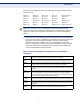
1 INTRODUCTION The Barricade Wireless Broadband Router (SMCWBR14S-N4) supports routing from an Internet Service Provider (ISP) connection (DSL or cable modem) to a local network. It is simple to configure and can be up and running in minutes. KEY HARDWARE FEATURES The following table describes the main hardware features of the Gateway Router. Table 1: Key Hardware Features Feature Description WAN Port One 100BASE-TX RJ-45 port for connecting to the Internet.
CHAPTER 1 | Introduction Description of Capabilities ◆ Easy setup through a Web browser on any operating system that supports TCP/IP. ◆ Compatible with all popular Internet applications. In addition, the Gateway Router offers full network management capabilities through an easy-to-configure web interface.
CHAPTER 1 | Introduction Package Contents ◆ Point-to-Point Tunneling Protocol — Provides a secure tunnel for remote client access to a PPTP security gateway. PPTP includes provisions for call origination and flow control required by ISPs.
CHAPTER 1 | Introduction Hardware Description Figure 1: Top Panel LED Indicators – 24 –
CHAPTER 1 | Introduction Hardware Description Figure 2: Rear Panel WPS Button Reset Button DC Power Socket RJ-45 WAN Port RJ-45 LAN Ports LED INDICATORS The Wireless Broadband Router includes seven status LED indicators, as described in the following figure and table.
CHAPTER 1 | Introduction Hardware Description Table 2: LED Behavior LED Status Description Power On Blue The unit is receiving power and is operating normally. Off There is no power currently being supplied to the unit. On/Blinking Blue The 802.11n radio is enabled and transmitting or receiving data through wireless links. Off The 802.11n radio is disabled. Blinking WPS authentication is in progress. Off WPS authentication is not in progress.
CHAPTER 1 | Introduction Hardware Description RESET BUTTON This button is used to restore the factory default configuration. If you hold down the button for 5 seconds or more, any configuration changes you may have made are removed, and the factory default configuration is restored to the Gateway Router. WPS BUTTON Press to automatically configure the Wireless Broadband Router with other WPS devices in the WLAN.
CHAPTER 1 | Introduction Hardware Description – 28 –
2 NETWORK PLANNING The Wireless Broadband Router is designed to be very flexible in its deployment options. It can be used as an Internet gateway for a small network, or as an access point to extend an existing wired network to support wireless users. It also supports use as a wireless bridge to connect up to four wired LANs. This chapter explains some of the basic features of the Wireless Broadband Router and shows some network topology examples in which the device is implemented.
CHAPTER 2 | Network Planning LAN Access Point Figure 4: Operating as an Internet Gateway Router Internet Service Provider Cable/DSL Modem ISP) Wireless AP/Router from d e n ssig .x) (IP a 68.2 WAN 92.1 1 : P (I LAN Notebook PC (IP: 192.168.2.x) LAN Switch Server (IP: 192.168.2.x) Desktop PC (IP: 192.168.2.
CHAPTER 2 | Network Planning Wireless Bridge Figure 5: Operating as an Access Point Server (IP: 192.168.2.x) Desktop PC (IP: 192.168.2.x) LAN Switch Notebook PC (IP: 192.168.2.x) Wireless AP/Router WIRELESS BRIDGE The IEEE 802.11 standard defines a Wireless Distribution System (WDS) for bridge connections between access points. The Wireless Broadband Router can use WDS to forward traffic on links between units. Up to four WDS links can be specified for the Wireless Broadband Router.
CHAPTER 2 | Network Planning Wireless Bridge Figure 7: Operating as a Wireless Repeater Internet Service Provider Cable/DSL Modem WDS Link Gateway Router (Gateway Mode) Gateway Router (Bridge Mode) Notebook PC Notebook PC – 32 –
3 INSTALLING THE GATEWAY ROUTER The Wireless Broadband Router has two basic operating modes that can be set through the web-based management interface. For information on setting the mode suitable for your network environment. See “Operation Mode” on page 54. ◆ Gateway Mode — A gateway mode that connects a wired LAN and wireless clients to an Internet access device, such as a cable or DSL modem. This is the factory set default mode.
CHAPTER 3 | Installing the Gateway Router Mounting on a Wall MOUNTING ON A WALL The Wireless Broadband Router should be mounted only to a wall or wood surface that is at least 1/2-inch plywood or its equivalent. To mount the unit on a wall, always use its wall-mounting bracket. The unit must be mounted with the RJ-45 cable connector oriented upwards to ensure proper operation. Figure 8: Wall Mounting Mounting Slots To mount on a wall, follow the instructions below. 1.
CHAPTER 3 | Installing the Gateway Router Mounting on a Horizontal Surface MOUNTING ON A HORIZONTAL SURFACE To keep the Wireless Broadband Router from sliding on the surface, the Wireless Broadband Router has four rubber feet on the bottom of the unit. It is recommended to select an uncluttered area on a sturdy surface, such as a desktop or table. The unit can also be protected by securing all attached cables to a table leg or other nearby fixed structure.
CHAPTER 3 | Installing the Gateway Router Bridge Mode Connections CAUTION: Use ONLY the power adapter supplied with the Wireless Broadband Router. Otherwise, the product may be damaged. When you power on the Wireless Broadband Router, verify that the Power LED turns on and that the other LED indicators start functioning as described under see “LED Indicators” on page 25. 4. Set up wireless devices by pressing the WPS button on the Wireless Broadband Router or by using the web interface.
CHAPTER 3 | Installing the Gateway Router Bridge Mode Connections 1. Using Ethernet cable connect the Wireless Broadband Router’s LAN and WAN ports to PCs or a LAN switch. 2. Power on the Wireless Broadband Router by connecting the AC power adapter and plugging it into a power source. CAUTION: Use ONLY the power adapter supplied with the Wireless Broadband Router. Otherwise, the product may be damaged.
4 INITIAL CONFIGURATION The Wireless Broadband Router offers a user-friendly web-based management interface for the configuration of all the unit’s features. Any PC directly attached to the unit can access the management interface using a web browser, such as Internet Explorer (version 6.0 or above). ISP SETTINGS If you are not sure of your connection method, please contact your Internet Service Provider.
CHAPTER 4 | Initial Configuration Home Page and Main Menu Figure 11: Login Page HOME PAGE AND MAIN MENU After logging in to the web interface, the Home page displays. The Home page shows the main menu and the method to access the Setup Wizard.
CHAPTER 4 | Initial Configuration Common Web Page Buttons COMMON WEB PAGE BUTTONS The list below describes the common buttons found on most web management pages: ◆ Apply – Applies the new parameters and saves them to memory. Also displays a screen to inform you when it has taken affect. Clicking ‘Apply’ returns to the home page. ◆ Cancel – Cancels the newly entered settings and restores the previous settings. ◆ Next – Proceeds to the next step. ◆ Back – Returns to the previous screen.
CHAPTER 4 | Initial Configuration Setup Wizard STEP 2 - SNTP The Step 2 page of the Wizard configures time zone and SNTP settings. SETTINGS Select a time zone according to where the device is operated. Click Next after completing the setup. Figure 14: Wizard Step 2 - Time and SNTP Settings The following items are displayed on this page: ◆ Current Time — Receives a time and date stamp from an SNTP server. ◆ Time Zone — Select the time zone that is applicable to your region.
CHAPTER 4 | Initial Configuration Setup Wizard STEP 3 - WAN The Step 3 page of the Wizard specifies the Internet connection SETTINGS - DHCP parameters for the Wireless Broadband Router’s WAN port. Click Next after completing the setup. By default, the access point WAN port is configured with DHCP enabled. The options are Static IP, DHCP (cable modem), PPPoE (ADSL), and PPTP. Each option changes the parameters that are displayed on the page.
CHAPTER 4 | Initial Configuration Setup Wizard NOTE: If you are unsure of the PC MAC address originally registered by your ISP, call your ISP and request to register a new MAC address for your account. Register the default MAC address of the Wireless Broadband Router. STEP 3 - WAN Configures a static IP for the WAN port.
CHAPTER 4 | Initial Configuration Setup Wizard ◆ MAC Clone — Some ISPs limit Internet connections to a specified MAC address. This setting allows you to manually change the MAC address of the Wireless Broadband Router's WAN interface to match the PC's MAC address provided to your ISP for registration. You can enter the registered MAC address manually by typing it in the boxes provided.
CHAPTER 4 | Initial Configuration Setup Wizard address to the Wireless Broadband Router, then click the “Clone your PC’s MAC Address” (Default: Disable) STEP 3 - WAN Enables the Point-to-Point Tunneling Protocol (PPTP) for implementing SETTINGS - PPTP virtual private networks. The service is provided in many European countries. Figure 18: Wizard Step 3 - WAN Settings - PPTP The following items are displayed on this page: ◆ Server IP — Sets the PPTP server IP Address.
CHAPTER 4 | Initial Configuration Setup Wizard ◆ Operation Mode — Enables and configures the keep alive time. ◆ Primary DNS Server — The IP address of the Primary Domain Name Server. A DNS maps numerical IP addresses to domain names and can be used to identify network hosts by familiar names instead of the IP addresses. To specify a DNS server, type the IP addresses in the text field provided. Otherwise, leave the text field blank.
CHAPTER 4 | Initial Configuration Setup Wizard ◆ Broadcast Network Name (SSID) — By default, the Wireless Broadband Router always broadcasts the SSID in its beacon signal. Disabling the SSID broadcast increases security of the network because wireless clients need to already know the SSID before attempting to connect. (Default: Enabled) ◆ AP Isolation — The Wireless Broadband Router will isolate communincation between all clients in order to protect them. Normally for users who are at hotspots.
CHAPTER 4 | Initial Configuration Setup Wizard – 48 –
SECTION II WEB CONFIGURATION This section provides details on configuring the Wireless Broadband Router using the web browser interface.
SECTION | Web Configuration – 50 –
5 OPERATION MODE The Wireless Broadband Router offers a user-friendly web-based management interface for the configuration of all the unit’s features. Any PC directly attached to the unit can access the management interface using a web browser, such as Internet Explorer (version 6.0 or above).
CHAPTER 5 | Operation Mode Logging In LOGGING IN It is recommended to make initial configuration changes by connecting a PC directly to one of the Wireless Broadband Router's LAN ports. The Wireless Broadband Router has a default IP address of 192.168.2.1 and a subnet mask of 255.255.255.0. If your PC is set to “Obtain an IP address automatically” (that is, set as a DHCP client), you can connect immediately to the web interface.
CHAPTER 5 | Operation Mode Logging In The home page displays the main menu items at the top of the screen and the Setup Wizard. See “Setup Wizard” on page 40. Figure 21: Home Page NOTE: The displayed pages and settings may differ depending on whether the unit is in Gateway or Bridge Mode. See “Operation Mode” on page 54.
CHAPTER 5 | Operation Mode Operation Mode OPERATION MODE The Operation Mode Configuration page allows you to set up the mode suitable for your network environment. Figure 22: Operation Mode (Gateway) ◆ Bridge Mode — An access point mode that extends a wired LAN to wireless clients. ◆ Gateway Mode — Normal gateway mode that connects a wired LAN and wireless clients to an Internet access device, such as a cable or DSL modem. This is the factory set default mode.
6 INTERNET SETTINGS The Internet Settings pages allow you to manage basic system configuration settings. It includes the following sections: ◆ “WAN Setting” on page 55 ■ “DHCP” on page 55 ■ “Static IP” on page 57 ■ “PPPoE” on page 58 ■ “PPTP” on page 59 ◆ “LAN Setting” on page 61 ◆ “Advanced Routing” on page 63 NOTE: In Bridge mode, the Wireless Broadband Router’s Internet Settings options are significantly reduced, with only LAN Settings and the Client List being available to the user.
CHAPTER 6 | Internet Settings WAN Setting Figure 23: DHCP Configuration The following items are displayed on this page: ◆ Hostname (Optional) — The hostname of the DHCP client. ◆ Primary DNS Server — The IP address of the Primary Domain Name Server. A DNS maps numerical IP addresses to domain names and can be used to identify network hosts by familiar names instead of the IP addresses. To specify a DNS server, type the IP addresses in the text field provided. Otherwise, leave the text field blank.
CHAPTER 6 | Internet Settings WAN Setting STATIC IP Configures a static IP for the WAN port. Figure 24: Static IP Configuration ◆ IP Address — The IP address of the Wireless Broadband Router. Valid IP addresses consist of four decimal numbers, 0 to 255, separated by periods. ◆ Subnet Mask — The mask that identifies the host address bits used for routing to specific subnets.
CHAPTER 6 | Internet Settings WAN Setting provided. Otherwise, connect only the PC with the registered MAC address to the Wireless Broadband Router, then click the “Clone your PC’s MAC Address” (Default: Disable) PPPOE Enables the Wireless Broadband Router IP address to be assigned automatically from an Internet service provider (ISP) through an ADSL modem using Point-to-Point Protocol over Ethernet (PPPoE). Figure 25: PPPoE Configuration ◆ PPPoE User Name — Sets the PPPoE user name for the WAN port.
CHAPTER 6 | Internet Settings WAN Setting ■ ◆ On Demand Mode: The maximum length of inactive time the unit will stay connected to the DSL service provider before disconnecting. (Default: 5 minutes) MAC Clone — Some ISPs limit Internet connections to a specified MAC address of one PC. This setting allows you to manually change the MAC address of the Wireless Broadband Router's WAN interface to match the PC's MAC address provided to your ISP for registration.
CHAPTER 6 | Internet Settings WAN Setting ◆ Password — Sets a PPTP password for the WAN port. (Default: pptp_password; Range: 1~32 characters) ◆ Verify Password — Prompts you to re-enter your chosen password. ◆ Address Mode — Sets a PPTP network mode. (Default: Static) ◆ IP Address — Sets the static IP address. (Default: 0.0.0.0, available when PPTP Network Mode is set to static IP.) ◆ Subnet Mask — Sets the static IP subnet mask. (Default: 255.255.255.
CHAPTER 6 | Internet Settings LAN Setting LAN SETTING The Wireless Broadband Router must have a valid IP address for management using a web browser and to support other features. The unit has a default IP address of 192.168.2.1. You can use this IP address or assign another address that is compatible with your existing local network. Click on “Internet Settings” followed by “LAN.
CHAPTER 6 | Internet Settings LAN Setting ◆ MAC Address — The shared physical layer address for the Wireless Broadband Router’s LAN ports. ◆ DHCP Server — Enable this feature to assign IP settings to wired and wireless clients connected to the Gateway Router. The IP address, subnet mask, default gateway, and Domain Name Server (DNS) address are dynamically assigned to clients.
CHAPTER 6 | Internet Settings Advanced Routing ◆ DNS Proxy — Enables DNS proxy on the LAN port. DNS Proxy receives DNS queries from the local network and forwards them to an Internet DNS server. (Default: Enable) ADVANCED ROUTING Routing setup allows a manual method to set up routing between networks. The network administrator configures static routes by entering routes directly into the routing table. Static routing has the advantage of being predictable and easy to configure.
CHAPTER 6 | Internet Settings Advanced Routing ◆ Destination — A destination network or specific host to which packets can be routed. ◆ Type — Defines the type of destination. (Options: Host/Net, Default: Host) ◆ Gateway — The IP address of the router at the next hop to which matching frames are forwarded. ◆ Interface — The selected interface to which a static routing subnet is to be applied. ◆ Comment — Enters a useful comment to help identify this route.
CHAPTER 6 | Internet Settings Advanced Routing ◆ Use — Count of lookups for the route. ◆ Interface — Interface to which packets for this route will be sent. ◆ Comment — Displays a useful comment to identify the routing rules. DYNAMIC ROUTE ◆ The Wireless Broadband Router supports RIP 1 and RIP 2 dynamic routing protocol. Routing Information Protocol (RIP) is the most widely used method for dynamically maintaining routing tables. RIP uses a distance vector-based approach to routing.
CHAPTER 6 | Internet Settings Advanced Routing – 66 –
7 WIRELESS CONFIGURATION The wireless settings section displays configuration settings for the access point functionality of the Wireless Broadband Router. It includes the following sections: ◆ “Basic Settings” on page 67 ◆ “WLAN Security” on page 69 ◆ “Advanced Settings” on page 76 ◆ “Wireless Distribution System (WDS)” on page 84 ◆ “Wi-Fi Protected Setup (WPS)” on page 88 ◆ “Station List” on page 90 BASIC SETTINGS The IEEE 802.
CHAPTER 7 | Wireless Configuration Basic Settings Figure 29: Basic Settings The following items are displayed on this page: ◆ Network Name (SSID) — The name of the wireless network service provided by the Wireless Broadband Router. Clients that want to connect to the network must set their SSID to the same as that of the Wireless Broadband Router.
CHAPTER 7 | Wireless Configuration WLAN Security ◆ Access Policy — The Wireless Broadband Router provides a MAC address filtering facility. The access policy can be set to allow or reject specific station MAC addresses. This feature can be used to connect known wireless devices that may not be able to support the configured security mode. ◆ Add a station MAC — Enter the MAC address of the station that you want to filter. MAC addresses must be entered in the format xx:xx:xx:xx:xx:xx.
CHAPTER 7 | Wireless Configuration WLAN Security ◆ WPA-PSK, WPA2-PSK, WPA-PSK_WPA2-PSK — See “WPA PreShared Key” on page 71 ◆ WPA, WPA2, WPA1_WPA2 — See “WPA Enterprise Mode” on page 72 ◆ 802.1X — See “IEEE 802.1X and RADIUS” on page 74 WIRED EQUIVALENT WEP provides a basic level of security, preventing unauthorized access to PRIVACY (WEP) the network, and encrypting data transmitted between wireless clients and an access point.
CHAPTER 7 | Wireless Configuration WLAN Security ◆ Default Key — Selects the WEP key number to use for authentication or data encryption. If wireless clients have all four WEP keys configured to the same values, you can change the encryption key to any of the settings without having to update the client keys. (Default: 1; Range: 1~4) ◆ WEP Keys 1 ~ 4 — Sets WEP key values. The user must first select ASCII or hexadecimal keys. Each WEP key has an index number.
CHAPTER 7 | Wireless Configuration WLAN Security ◆ WPA Algorithms — Selects the data encryption type to use. (Default is determined by the Security Mode selected.) ■ ■ ■ TKIP — Uses Temporal Key Integrity Protocol (TKIP) keys for encryption. WPA specifies TKIP as the data encryption method to replace WEP. TKIP avoids the problems of WEP static keys by dynamically changing data encryption keys. AES — Uses Advanced Encryption Standard (AES) keys for encryption.
CHAPTER 7 | Wireless Configuration WLAN Security Figure 33: Security Mode - WPA Security Mode — Configures the WPA and WPA2 security modes used by clients. When using WPA or WPA2, be sure there is a RADIUS server in the connected wired network, and that the RADIUS settings are configured. See “IEEE 802.1X and RADIUS” on page 74 for more information. (Default: Disable) ◆ WPA — Clients using WPA with an 802.1X authentication method are accepted for authentication.
CHAPTER 7 | Wireless Configuration WLAN Security bit key. Use of AES-CCMP encryption is specified as a standard requirement for WPA2. Before implementing WPA2 in the network, be sure client devices are upgraded to WPA2-compliant hardware. ■ TKIP/AES — Uses either TKIP or AES keys for encryption. WPA and WPA2 mixed modes allow both WPA and WPA2 clients to associate to a common SSID. In mixed mode, the unicast encryption type (TKIP or AES) is negotiated for each client.
CHAPTER 7 | Wireless Configuration WLAN Security Figure 34: Security Mode - 802.1X Security Mode — Configures the 802.1X security mode used by clients. When using 802.1X, either with WPA/WPA2 or on its own, be sure there is a configured RADIUS server in the connected wired network. (Default: Disable) 802.1X WEP: Selects WEP keys for data encryption. When enabled, WEP encryption keys are automatically generated by the RADIUS server and distributed to all connected clients.
CHAPTER 7 | Wireless Configuration Advanced Settings ADVANCED SETTINGS The Advanced Settings page includes additional parameters concerning the wireless network, including HT Physical Mode, and Wi-Fi Multimedia settings. NOTE: There are several variables to consider when selecting a radio mode that make it fully functional. Simply selecting the mode you want is not enough to ensure full compatibility for that mode. Information on these variables may be found in the HT Physcial Mode Setting section.
CHAPTER 7 | Wireless Configuration Advanced Settings ■ ■ ■ ■ ◆ 11g only: Both 802.11g and 802.11n clients will be able to communicate with the Wireless Broadband Router, but the 802.11n clients will be limited to 802.11g protocols and data transmission rates (up to 54 Mbps). Any 802.11b clients will not be able to communicate with the Wireless Broadband Router. 11n only: Only 802.11n clients will be able to communicate with the Wireless Broadband Router (up to 150 Mbps). 11g/n mixed: Both 802.
CHAPTER 7 | Wireless Configuration Advanced Settings The following items are displayed in this section on this page: ◆ HT Channel Bandwidth — The Wireless Broadband Router provides a channel bandwidth of 40 MHz by default giving an 802.11g connection speed of 108 Mbps (sometimes referred to as Turbo Mode) and a 802.11n connection speed of up to 150 Mbps. Setting the HT Channel Bandwidth to 20 MHz slows connection speed for 802.11g and 802.
CHAPTER 7 | Wireless Configuration Advanced Settings ADVANCED WIRELESS The Advanced Wireless section on the Wireless Settings Advanced page includes additional radio parameters. Figure 37: Advanced Wireless Settings The following items are displayed in this section on this page: ◆ BG Protection Mode — Enables a backward compatible protection mechanism for 802.11b clients. There are three modes: (Default: Auto) ■ ■ ■ Auto — The unit enables its protection mechanism for 802.
CHAPTER 7 | Wireless Configuration Advanced Settings and forward them after every beacon. Using smaller DTIM intervals delivers broadcast/multicast frames in a more timely manner, causing stations in Power Save mode to wake up more often and drain power faster. Using higher DTIM values reduces the power used by stations in Power Save mode, but delays the transmission of broadcast/multicast frames.
CHAPTER 7 | Wireless Configuration Advanced Settings ◆ Packet Aggregate — A performance enhancement that combines data packets together when the feature is supported by compatible clients. (Default: Enabled) WI-FI MULTIMEDIA The Wireless Broadband Router implements Quality of Service (QoS) using the Wi-Fi Multimedia (WMM) standard. Using WMM, the access point is able to prioritize traffic and optimize performance when multiple applications compete for wireless network bandwidth at the same time.
CHAPTER 7 | Wireless Configuration Advanced Settings The following items are displayed in this section on this page: ◆ WMM — Sets the WMM operational mode on the access point. When enabled, the QoS capabilities are advertised to WMM-enabled clients in the network. WMM must be supported on any device trying to associated with the access point. Devices that do not support this feature will not be allowed to associate with the access point.
CHAPTER 7 | Wireless Configuration Advanced Settings the CWMin value. Specify the CWMin value in the range 0-15 microseconds. Note that the CWMin value must be equal or less than the CWMax value. ◆ CWMax (Maximum Contention Window) — The maximum upper limit of the random backoff wait time before wireless medium access can be attempted. The contention window is doubled after each detected collision up to the CWMax value. Specify the CWMax value in the range 0-15 microseconds.
CHAPTER 7 | Wireless Configuration Wireless Distribution System (WDS) WIRELESS DISTRIBUTION SYSTEM (WDS) The radio interface can be configured to operate in a mode that allows it to forward traffic directly to other Wireless Gateway Router units. This feature can be used to extend the range of the wireless network to reach remote clients, or to link disconnected network segments to an Internet connection.
CHAPTER 7 | Wireless Configuration Wireless Distribution System (WDS) Figure 42: WDS Configuration Example Internet Service Provider WDS Link Cable/DSL Modem WD SL ink WD Operation Mode: Gateway WDS Mode: Bridge DHCP Server: Enable LAN IP Address: 192.168.2.1 Operation Mode: Bridge WDS Mode: Repeater DHCP Server: Disable LAN IP Address: 192.168.2.2 SL ink Operation Mode: Gateway WDS Mode: Lazy DHCP Server: Disable LAN IP Address: 192.168.2.
CHAPTER 7 | Wireless Configuration Wireless Distribution System (WDS) Figure 43: WDS Configuration The WDS settings configure WDS related parameters. Up to four MAC addresses can be specified for each unit in the WDS network. WDS links may either be manually configured (Bridge and Repeater modes) or autodiscovered (Lazy mode).
CHAPTER 7 | Wireless Configuration Wireless Distribution System (WDS) ◆ WDS Mode — Selects the WDS mode of the SSID. (Options: Disable, Lazy, Bridge, Repeater. Default: Disable) ■ ■ Disable: WDS is disabled. Lazy: Operates in an automatic mode that detects and learns WDS peer addresses from received WDS packets, without the need to configure a WDS MAC list entry.
CHAPTER 7 | Wireless Configuration Wi-Fi Protected Setup (WPS) WI-FI PROTECTED SETUP (WPS) Wi-Fi Protected Setup (WPS) is designed to ease installation and activation of security features in wireless networks. WPS has two basic modes of operation, Push-button Configuration (PBC) and Personal Identification Number (PIN). The WPS PIN setup is optional to the PBC setup and provides more security.
CHAPTER 7 | Wireless Configuration Wi-Fi Protected Setup (WPS) Figure 45: WPS Configuration WPS Summary — Provides detailed WPS statistical information. ◆ WPS Current Status — Displays if there is currently any WPS traffic connecting to the Wireless Broadband Router. (Options: Start WSC Process; Idle) ◆ WPS Configured — States if WPS for wireless clients has been configured for this device. ◆ WPS SSID — The service set identifier for the unit. ◆ WPS Auth Mode — The method of authentication used.
CHAPTER 7 | Wireless Configuration Station List WPS Config — Configures WPS settings for the Wireless Broadband Router. ◆ WPS Mode — Selects between methods of broadcasting the WPS beacon to network clients wanting to join the network: ■ ■ PIN: The Wireless Broadband Router, along with other WPS devices, such as notebook PCs, cameras, or phones, all come with their own eight-digit PIN code.
8 FIREWALL CONFIGURATION The Wireless Broadband Router provides extensive firewall protection by restricting connection parameters to limit the risk of intrusion and defending against a wide array of common hacker attacks.
CHAPTER 8 | Firewall Configuration MAC/IP/Port Filtering Figure 47: MAC/IP/Port Filtering ◆ MAC/IP/Port Filtering — Enables or disables MAC/IP/Port Filtering. (Default: Disable) ◆ Default Policy — When MAC/IP/Port Filtering is enabled, the default policy will be enabled. If you set the default policy to “Dropped”, all incoming packets that don’t match the rules will be dropped. If the policy is set to "Accepted," all incoming packets that don't match the rules are accepted.
CHAPTER 8 | Firewall Configuration MAC/IP/Port Filtering ◆ Source IP Address — Specifies the source IP address to block or allow traffic from. ◆ Protocol — Specifies the destination port type, TCP, UDP or ICMP. (Default: None). ◆ Destination Port Range — Specifies the range of destination port to block traffic from the specified LAN IP address from reaching. ◆ Source Port Range — Specifies the range of source port to block traffic from the specified LAN IP address from reaching.
CHAPTER 8 | Firewall Configuration Virtual Server Settings (Port Forwarding) VIRTUAL SERVER SETTINGS (PORT FORWARDING) Virtual Server (sometimes referred to as Port Forwarding) is the act of forwarding a network port from one network node to another. This technique can allow an external user to reach a port on a private IP address (inside a LAN) from the outside through a NAT-enabled router. (Maximum 32 entries are allowed.
CHAPTER 8 | Firewall Configuration DMZ CURRENT VIRTUAL The Current Port Forwarding Table displays the entries that are allowed to SERVERS IN SYSTEM forward packets through the Wireless Broadband Router’s firewall. ◆ No. — The table entry number. ◆ IP Address — Displays an IP address on the local network to allow external access to. ◆ Port Mapping — Displays the port the server is mapped. ◆ Protocol — Displays the protocol used for forwarding of this port.
CHAPTER 8 | Firewall Configuration System Security SYSTEM SECURITY The Wireless Broadband Router includes the facility to manage it from a remote location. The unit can also be sent a ping message from a remote location. Figure 50: System Security ◆ Remote Management — Denies or allows management access to the Gateway Router through the WAN interface. (Default: Deny) ◆ Ping from WAN Filter — When enabled, the Gateway Router does not respond to ping packets received on the WAN port.
CHAPTER 8 | Firewall Configuration Content Filtering CONTENT FILTERING The Wireless Broadband Router provides a variety of options for blocking Internet access based on content, URL and host name. Figure 51: Content Filtering Web URL Filter Settings — By filtering inbound Uniform Resource Locators (URLs) the risk of compromising the network can be reduced. URLs are commonly used to point to websites. By specifying a URL or a keyword contained in a URL traffic from that site may be blocked.
CHAPTER 8 | Firewall Configuration Content Filtering ◆ Add a Host Filter — Enters the keyword for a host filtering.
9 ADMINISTRATION SETTINGS The Wireless Broadband Router’s Administration Settings menu provides the same configuration options in both Gateway and Bridge Mode. These settings allow you to configure a management access password, set the system time, upgrade the system software, display the system status and statistics.
CHAPTER 9 | Administration Settings System Management SYSTEM MANAGEMENT The System Management commands allow you to change the language settings displayed in the interface, and change the user name and password. Figure 52: System Management LANGUAGE SETTINGS You can change the language displayed in web interface. Chooses the appropriate language of your choice from the drop-down list, then click “Apply”. (Options: English, Traditional Chinese.
CHAPTER 9 | Administration Settings SNTP Settings SNTP SETTINGS The System Management page allows you to manually configure time settings or enable the use of a Simple Network Time Protocol (SNTP) or NTP server. Figure 53: SNTP Settings ◆ Current Time — Displays the current system time on the unit. ◆ Sync with host — Updates the unit's time from the web management PC's system time. ◆ Time Zone — Specifies the time zone in relation to Greenwich Mean Time (GMT).
CHAPTER 9 | Administration Settings DDNS Settings DDNS SETTINGS Dynamic DNS (DDNS) provides users on the Internet with a method to tie a specific domain name to the unit’s dynamically assigned IP address. DDNS allows your domain name to follow your IP address automatically by changing your DNS records when your IP address changes. The Wireless Broadband Router provides access to three DDNS service providers, DynDns.org, Non-IP.com and ZoneEdit.com.
CHAPTER 9 | Administration Settings Upgrade Firmware UPGRADE FIRMWARE You can update the Wireless Broadband Router firmware by using the Firmware Update facility. Figure 55: Upgrade Firmware Firmware Upgrade — Allows you to upload new firmware manually by specifying a file path. Make sure the firmware you want to use is on the local computer by clicking Browse to search for the firmware to be used for the update.
CHAPTER 9 | Administration Settings Configuration Settings CONFIGURATION SETTINGS The Configuration Setting page allows you to save the Wireless Broadband Router’s current configuration or restore a previously saved configuration back to the device. Figure 56: Configuration Settings ◆ Export Settings — Saves the current configuration to a file locally. ◆ Import Settings — Allows the user to load previously saved configuration files from a local source.
CHAPTER 9 | Administration Settings System Status SYSTEM STATUS The System Information page displays basic system information and the displayed settings are for status information only and are not configurable on this page. This information is split into the three sections that follow. Figure 57: System Status (Gateway Mode) System Info — Displays the basic system information in both Bridge and Gateway Modes: ◆ Firmware Version — The version number of the current Wireless Broadband Router software.
CHAPTER 9 | Administration Settings System Status ◆ Default Gateway — The default gateway is the IP address of the router for the Wireless Broadband Router, which is used if the requested destination address is not on the local subnet. ◆ Primary DNS Server / Secondary DNS Server — The IP address of Domain Name Servers. A DNS maps numerical IP addresses to domain names and can be used to identify network hosts by familiar names instead of the IP addresses.
CHAPTER 9 | Administration Settings Statistics STATISTICS The Wireless Broadband Router Traffic Statistics - Interfaces window displays received and transmitted packet statistics for all interfaces on the Wireless Broadband Router. Figure 58: Statistics The following items are displayed on this page: ◆ Memory total — The total memory of this Wireless Broadband Router. ◆ Memory left — The available memory of this Wireless Broadband Router.
CHAPTER 9 | Administration Settings System Log ◆ Tx packets — Displays the total number of packets transmitted by the specified interfaces. ◆ Tx bytes — Displays the total number of bytes transmitted by the specified interface. SYSTEM LOG The Wireless Broadband Router supports a logging process that controls error messages saved to memory or sent to a Syslog server. The logged messages serve as a valuable tool for isolating Wireless Broadband Router and network problems.
CHAPTER 9 | Administration Settings System Log – 109 –
SECTION III APPENDICES This section provides additional information and includes these items: ◆ “Troubleshooting” on page 111 ◆ “Hardware Specifications” on page 114 ◆ “Cables and Pinouts” on page 116 ◆ “Glossary” on page 123 ◆ “Index” on page 113 – 110 –
A TROUBLESHOOTING DIAGNOSING LED INDICATORS Table 4: LED Indicators Symptom Action Power/LAN LEDs are off ◆ The AC power adapter may be disconnected. Check connections between the Gateway Router, the power adapter, and the wall outlet. WLAN LED is off ◆ The access point radio has been disabled through it’s web management interface. Access the management interface using a web browser to enable the radio. LAN LEDs are off (when port connected) ◆ ◆ Verify that the Gateway Router is powered on.
APPENDIX A | Troubleshooting Before Contacting Technical Support ■ ■ Check that you have a valid network connection to the Gateway Router and that the Ethernet port or the wireless interface that you are using has not been disabled. If you are connecting to the Gateway Router through the wired Ethernet interface, check the network cabling between the management station and the Gateway Router.
APPENDIX A | Troubleshooting Before Contacting Technical Support – 113 –
B HARDWARE SPECIFICATIONS PORT INTERFACES WAN: 10/100BASE-TX port, RJ-45 connector, auto MDI/X (100-ohm, UTP cable; Category 5 or better) LAN 1~4: 10/100BASE-TX port, RJ-45 connector, auto MDI/X (100-ohm, UTP cable; Category 5 or better) AC POWER ADAPTER Input: 100~240 VAC, 50/60 Hz Output: 5 V/ 1 A LED INDICATORS Power, WLAN (Wireless Local Area Network), WPS (Wi-Fi Protected Setup), WAN (Wide Area Network), LAN 1~4 (Local Area Network).
APPENDIX B | Hardware Specifications STANDARDS UL60950-1/CSA22.2 No. 60950-1 EN 60950-1/IEC 60950-1 ETSI EN 300 019-2-1 Class 1.2 (Storage) ETSI EN 300 019-2-2 Class 2.3 (Packaged) ETSI EN 300 019-2-3 Class 3.
C CABLES AND PINOUTS TWISTED-PAIR CABLE ASSIGNMENTS For 10/100BASE-TX connections, a twisted-pair cable must have two pairs of wires. For 1000BASE-T connections the twisted-pair cable must have four pairs of wires. Each wire pair is identified by two different colors. For example, one wire might be green and the other, green with white stripes. Also, an RJ-45 connector must be attached to both ends of the cable. NOTE: Each wire pair must be attached to the RJ-45 connectors in a specific orientation.
APPENDIX C | Cables and Pinouts 10/100BASE-TX Pin Assignments 10/100BASE-TX PIN ASSIGNMENTS Use unshielded twisted-pair (UTP) or shielded twisted-pair (STP) cable for RJ-45 connections: 100-ohm Category 3 or better cable for 10 Mbps connections. Also be sure that the length of any twisted-pair connection does not exceed 100 meters (328 feet).
APPENDIX C | Cables and Pinouts Crossover Wiring Figure 61: Straight-through Wiring EIA/TIA 568B RJ-45 Wiring Standard 10/100BASE-TX Straight-through Cable White/Orange Stripe Orange End A White/Green Stripe 1 2 3 4 5 6 7 8 Blue White/Blue Stripe Green White/Brown Stripe 1 2 3 4 5 6 7 8 End B Brown CROSSOVER WIRING If the twisted-pair cable is to join two ports and either both ports are labeled with an “X” (MDI-X) or neither port is labeled with an “X” (MDI), a crossover must be implemented in the
D LICENSE INFORMATION This product includes copyrighted third-party software subject to the terms of the GNU General Public License (GPL), GNU Lesser General Public License (LGPL), or other related free software licenses. The GPL code used in this product is distributed WITHOUT ANY WARRANTY and is subject to the copyrights of one or more authors. For details, refer to the section "The GNU General Public License" below, or refer to the applicable license as included in the source-code archive.
APPENDIX D | License Information The GNU General Public License GNU GENERAL PUBLIC LICENSE TERMS AND CONDITIONS FOR COPYING, DISTRIBUTION AND MODIFICATION 1. This License applies to any program or other work which contains a notice placed by the copyright holder saying it may be distributed under the terms of this General Public License.
APPENDIX D | License Information The GNU General Public License a). Accompany it with the complete corresponding machine-readable source code, which must be distributed under the terms of Sections 1 and 2 above on a medium customarily used for software interchange; or, b).
APPENDIX D | License Information The GNU General Public License This section is intended to make thoroughly clear what is believed to be a consequence of the rest of this License. 9.
GLOSSARY 10BASE-T IEEE 802.3-2005 specification for 10 Mbps Ethernet over two pairs of Category 3 or better UTP cable. 100BASE-TX IEEE 802.3-2005 specification for 100 Mbps Fast Ethernet over two pairs of Category 5 or better UTP cable. 1000BASE-T IEEE 802.3ab specification for 1000 Mbps Gigabit Ethernet over four pairs of Category 5 or better UTP cable. ACCESS POINT An internetworking device that seamlessly connects wired and wireless networks.
GLOSSARY the Bootstrap Protocol (BOOTP), adding the capability of automatic allocation of reusable network addresses and additional configuration options. ENCRYPTION Data passing between the access point and clients can use encryption to protect from interception and evesdropping. ETHERNET A popular local area data communications network, which accepts transmission from computers and terminals. FTP File Transfer Protocol: A TCP/IP protocol used for file transfer.
GLOSSARY beacon, and automatically reset their SSID to allow immediate connection to the nearest access point. ODFM Orthogonal Frequency Division Multiplexing: OFDM allows multiple users to transmit in an allocated band by dividing the bandwidth into many narrow bandwidth carriers. SSID Service Set Identifier: An identifier that is attached to packets sent over the wireless LAN and functions as a password for joining a particular radio cell; i.e., Basic Service Set (BSS).
GLOSSARY WEP Wired Equivalent Privacy: WEP is based on the use of security keys and the popular RC4 encryption algorithm. Wireless devices without a valid WEP key will be excluded from network traffic. WPA-PSK WPA Pre-shared Key: WPA-PSK can be used for small office networks with a limited number of users that may not need a high level of security. WPAPSK provides a simple security implementation that uses just a pre-shared password for network access.
SMCWBR14S-N4