Copyright Information furnished by SMC Networks, Inc. (SMC) is believed to be accurate and reliable. However, no responsibility is assumed by SMC for its use, or for any infringements of patents or other rights of third parties which may result from its use. No license is granted by implication or otherwise under any patent or patent rights of SMC. SMC reserves the right to change specifications at any time without notice. The products and programs described in this User Guide are licensed products of SMC.
Compliances FCC - Class B This equipment has been tested and found to comply with the limits for a Class B digital device, pursuant to Part 15 of the FCC Rules. These limits are designed to provide reasonable protection against harmful interference in a residential installation. This equipment generates uses and can radiate radio frequency energy and, if not installed and used in accordance with instructions, may cause harmful interference to radio communications.
EC Conformance Declaration – Class B SMC contact for these products in Europe is: SMC Networks Europe, Edificio Conata II Calle Fructuos Gelabert 6-8, 2o, 4a 08970 – Sant Joan Despi Barcelona, Spain This equipment complies with the requirements relating to electromagnetic compatibility, EN 55022/A1 Class B, and EN 50082-1.
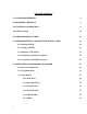
TABLE OF CONTENTS 1 | SYSTEM REQUIREMENTS 8 2 | EQUIPMENT CHECKLIST 8 3 | FUNCTIONS AND FEATURES 9 4 | PANEL LAYOUT 10 5 | HARDWARE INSTALLATION 11 6 | NETWORK SETTINGS AND SOFTWARE INSTALLATION 12 6.1 | Installing TCP/IP 12 6.2 | Setting up TCP/IP 12 6.3 | Obtaining an IP Address 13 6.4 | Configuring a Macintosh Computer 13 6.5 | Verifying Your TCP/IP Connection 14 7 | CONFIGURING YOUR BROADBAND ROUTER 15 v 7.1 | Browser Configuration 15 7.2 | Web Management 15 7.
7.3.8 | BigPond 19 7.3.9 | L2TP 20 7.4 | Advanced Setup – SYSTEM 7.4.1 | Time Zone 21 7.4.2 | Password Settings 22 7.4.3 | Remote Management 22 7.4.4 | Syslog Server 23 7.5 | Advanced Setup - WAN vi 21 24 7.5.1 | Dynamic IP 24 7.5.2 | PPPoE 25 7.5.3 | PPTP 26 7.5.4 | Static IP 27 7.5.6 | BigPond 27 7.5.7 | L2TP 28 7.6 | Advanced Setup - LAN 29 7.7 | Advanced Setup - NAT 30 7.7.1 | Virtual Server 30 7.7.2 | Special Applications 31 7.8 | Advanced Setup - FIREWALL 32 7.8.
.9 | Advanced Setup - SNMP 37 7.10 | Advanced Setup - ROUTING 38 7.11 | Advanced Setup - MISCELLANEOUS 39 7.12 | Advanced Setup – DISPLAY STATUS 40 7.13 | DDNS (Dynamic DNS) 40 7.14 | UPnP (Universal Plug-and-Play) 41 7.15 | Tools 41 7.16 | Status 42 8 | LPR PRINTING GUIDE 43 8.1 | Installing a LPR Print Server on Windows XP and Windows 2000 43 8.2 | Installing the Printe Server Monitor for Windows XP, 2000, NT 49 8.3 | Installing the Printer Server on Windows 98/SE/ME 53 8.
1 | System Requirements • • • • • Internet access from your local telephone company or Internet Service Provider (ISP) using a DSL modem, cable modem, Dial-Up modem, or ISDN modem A PC using a fixed IP address or dynamic IP address assigned via DHCP, as well as a Gateway server address and DNS server address from your service provider A computer equipped with a 10 Mbps, 100 Mbps, or 10/100 Mbps Fast Ethernet card, or a USB-to-Ethernet converter TCP/IP network protocol installed on each PC that needs to acc
3 | Functions and Features Broadband Modem and NAT Router Connects multiple computers to a broadband (cable or DSL) modem, and/or Ethernet router to access the Internet. 10/100 Mbps Ethernet Interface Provides a 10/100 Base-TX interface to connect to a DSL or cable modem for broadband Internet access. Equipped with a 4-port auto-sensing Ethernet switch. Auto-sensing Ethernet Switch Printer sharing Embedded a print server to allow all of the networked computers to share one printer.
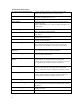
Allows you to determine which physical interface address to use for outgoing IP data grams. If you have more than one router and subnet, enable the routing table to allow packets to find the proper routing path and the different subnets to communicate with each other. Routing Table Supported 4 | Panel Layout The following figure shows the front panel layout, which is followed by a table describing in detail the status and function of each LED.
Port Type Description 5 VDC Receptor for power adapter: 5 VDC, 2 A (minimum) WAN This is the connection for the Ethernet cable to the Ethernet port on the cable or DSL modem These are the connections for Ethernet cables to your Ethernet enabled computers Port 1–4 USB PRINTER USB Ports for USB printer DB25 Printer Port 5 | Hardware Installation The router can be placed anywhere in your office or home. No special wiring or cooling requirements are necessary.
6 | Network Settings and Software Installation Default Settings IP Address Subnet Mask Administrator Password User Password 192.168.2.1 255.255.255.0 smcadmin password You must first verify that the TCP/IP communication protocol is properly installed and the computer is configured to get its IP address via the DHCP Server that is built-into this router. If you have not previously installed TCP/IP protocols on your client PCs, refer to the following section. 6.1 Installing TCP/IP Windows 95/98/Me 1.
Windows NT 1. From the Windows desktop click Start/Settings/Control Panel. 2. Double-click the Network icon. 3. Click on the Protocols tab. 4. Double-click TCP/IP Protocol. 5. Click on the IP Address tab. 6. In the Adapter drop-down list, be sure your Ethernet adapter is selected. 7. Click on “Obtain an IP address from a DHCP server.” 8. Click OK to close the window. 9. Windows may copy files and will then prompt you to restart your system. Click Yes and your computer will shut down and restart.
6.5 | Verifying Your TCP/IP Connection After installing the TCP/IP communication protocols and configuring an IP address in the same network as the Router, use the ping command to check if your computer has successfully connected to the Router. The following example shows how the ping procedure can be executed in an MS-DOS window. First, execute the ping command: Ping 192.168.2.1 If a message similar to the following appears: Pinging 192.168.2.1 with 32 bytes of data: Reply from 192.168.2.
7 | Configuring Your Broadband Router Before you attempt to log into the web-based Administration, please verify the following. 1. Your browser is configured properly (see below). 2. Disable any firewall or security software that may be running. 3. Confirm that you have a good link LED where your computer is plugged into the Router. If you don’t have a link light, then try another cable until you get a good link. 7.
7.3 | Setup Wizard 7.3.1 Time Zone After logging into the web management, click on SETUP WIZARD on the top left navigation panel. The first item is Time Zone. For accurate timing of client filtering and log events, you need to set the time zone. Select your time zone from the drop-down list. 7.3.2 Broadband Type The following screen lets you select a WAN type. Click one of the five options and then click [Next].
7.3.4 Cable Modem The cable modem option allows you to configure a host name and MAC Address. The Host Name is optional, but may be required by some ISPs. The default MAC address is set to the WAN’s physical interface on the Router. Use this address when registering for Internet service, and do not change it unless required by your ISP.
7.3.6 PPPoE xDSL Enter the PPPoE User Name and Password assigned by your Service Provider. The Service Name is normally optional, but may be required by some service providers. Leave the Maximum Transmission Unit (MTU) at the default value unless you have a particular reason to change it. Enter a Maximum Idle Time (in minutes) to define a maximum period of time for which the Internet connection is maintained during inactivity.
7.3.7 PPTP Point-to-Point Tunneling Protocol is a common connection method used for xDSL connections in Europe. It can be used to join different physical networks using the Internet as an intermediary. If you have been provided with the information as shown on the screen, enter the assigned IP address, subnet mask, default gateway IP address, user ID and password, and PPTP Gateway. Configure the Connect mode option to the desired settings.
7.3.9 L2TP Layer 2 Tunneling Protocol is a common connection method used for xDSL connections in Europe. It can be used to join different physical networks using the Internet as an intermediary. If you have been provided with the information as shown on the screen, enter the assigned IP address, subnet mask, default gateway IP address, user ID and password, and L2TP Gateway. Configure the Connect mode option to the desired settings.
7.4 | Advanced Setup – SYSTEM 7.4.1 Time Zone Use the section below to configure the Barricade's system time. Select your time zone and configure the daylight savings option based on your location. This information is used for the time/date parental rules you can configure with the Barricade's Advanced Firewall. This information is also used for your network logging.
7.4.2 Password Settings Use this section to configure the 2 password accounts and idle time-out setting for your Barricade Router. There are 2 levels of admin access for this Router: The Administrator account has Read/Write permission to view and change any settings. The default password for this account is "smcadmin". The User account has Read-Only permissions to view but not change the settings. The default password for this account is "password". 7.4.
7.4.4 Syslog Server The Syslog Server tool will automatically download the Barricade log to the server IP address specified by the user. Enter the Server LAN IP Address and select the Enable radio button to enable this function. The broadband router is also able to send the log files to a specific email address. Simply enter the IP address of your mail server in the SMTP Server box, enter the email addresses of the recipients who will receive the email log, and put in your username and password.
7.5 | Advanced Setup - WAN 7.5.1 Dynamic IP The cable modem option allows you to configure a host name and MAC Address. The Host Name is optional, but may be required by some ISPs. The default MAC address is set to the WAN’s physical interface on the Router. Use this address when registering for Internet service, and do not change it unless required by your ISP.
7.5.2 PPPoE Enter the PPPoE User Name and Password assigned by your Service Provider. The Service Name is normally optional, but may be required by some service providers. Leave the Maximum Transmission Unit (MTU) at the default value unless you have a particular reason to change it. Enter a Maximum Idle Time (in minutes) to define a maximum period of time for which the Internet connection is maintained during inactivity.
7.5.3 PPTP Point-to-Point Tunneling Protocol is a common connection method used for xDSL connections in Europe. It can be used to join different physical networks using the Internet as an intermediary. If you have been provided with the information as shown on the screen, enter the assigned IP address, subnet mask, default gateway IP address, user ID and password, and PPTP Gateway. Configure the Connect mode option to the desired settings.
7.5.4 Static IP Some Internet Service Providers may assign a fixed (static) IP address. If you have been provided with this information, choose this option and enter the assigned IP address, gateway IP address, DNS IP addresses, and subnet mask. 7.5.6 BigPond If you use the BigPond Internet Service which is available in Australia, enter your username and password and apply the changes.
7.5.7 L2TP Layer 2 Tunneling Protocol is a common connection method used for xDSL connections in Europe. It can be used to join different physical networks using the Internet as an intermediary. If you have been provided with the information as shown on the screen, enter the assigned IP address, subnet mask, default gateway IP address, user ID and password, and L2TP Gateway. Configure the Connect mode option to the desired settings.
7.6 | Advanced Setup - LAN This is the local IP address of the router. All networked computers must use the LAN IP address of the router as their default Gateway. However, if necessary, it can be changed. Here you can configure the LAN IP address for the router and enable/disable the DHCP server for dynamic client address allocation. You can change the lease time if necessary as well. By default this is set to “One Week”.
Clicking on the “Client List” link brings up the DHCP Client Table, showing all the clients that have obtained DHCP addresses from the router: 7.7 | Advanced Setup - NAT 7.7.1 | Virtual Server The firewall of the router filters out unrecognized packets to protect your intranet. This means that all network hosts are invisible to the outside world. However, some of the hosts can be made accessible by enabling the Virtual Server mapping. A virtual server is defined as a Service Port.
For example, if you have an FTP server (port 21) at 192.168.123.1, a Web server (port 80) at 192.168.123.2, and a server at 192.168.123.6, you need to specify the following virtual server mapping as shown in the table below: Service Port 21 80 1723 Server IP Enable 192.168.123.1 192.168.123.2 192.168.123.6 X X X The “IP Address” section should contain the IP of the server computer in the LAN network that will be providing the virtual services.
The router provides some predefined settings. To add a predefined setting to your list, select an application and click “Copy to”. Note: Only one computer can use the Special Application tunnels at any given time. For a full list of ports and the services that run on them, see http://www.iana.org/assignments/port-numbers 7.8 | Advanced Setup - FIREWALL 7.8.1 | Network Filters The Broadband Router firewall includes comprehensive Outbound and Inbound Network Packet Filters.
You can apply up to 8 rules for each direction, inbound or outbound. For each rule you can define the following: • Source IP address • Source port address • Destination IP address • Destination port address • Protocol: TCP or UDP, or both • Use Rule # You can define a single IP address (4.3.123.254) or a range of IP addresses (4.3.123.254 – 4.3.2.254) for the source or destination IP address. A blank IP implies that all IP addresses are included.
7.8.3 | MAC Filter MAC Address Filtering allows you assign different access rights to various users and you can also assign a specific IP address to a certain MAC address. Select the Enable radio button to enable the MAC Address Control. All of the settings on this screen take effect when Enable is checked. • • MAC Address: This is the unique address of a specific client. IP Address: Expected IP address of the corresponding client. You can keep this text field blank if you do not know the address.
7.8.4 | Schedule Rule Set scheduled times to be used to control what time of day a service or set of services is enabled. Use this section to configure up to 10 Schedule Rules to limit network access based on time and day. To create a schedule rule click the [Add Schedule Rule...] link below. Enter a rule name into the text field next to “Name of Rule 1”. Click Save Settings to save your settings.
The Schedule Rule screen appears. It now shows your setting for Rule 1. If you need to make changes to your setting, click the Edit button. If you want to delete Rule 1, click the Delete button. 7.8.5 | Advanced In this section you can enable/disable Stateful Packet Inspection (SPI), Discard Ping from WAN, and PPTP and IPSec Passthrough types. When Discard Ping From WAN is enabled, computers on the Internet will not get a reply back from the Broadband Router when it is being “ping”ed.
7.8.6 | DMZ If you have a local client PC that cannot run an Internet application properly from behind the NAT firewall, then you can open the client up to unrestricted two-way Internet access by defining a Virtual DMZ Host. 7.9 | Advanced Setup - SNMP The Simple Network Management Protocol (SNMP) lets you manage a computer network remotely by polling and setting terminal values and monitoring network events. • • • 37 Enable SNMP: You can check Local, Remote, or both options to enable the SNMP function.
7.10 | Advanced Setup - ROUTING The Routing Table lets you determine which physical interface address to use for outgoing IP data grams. If you have more than one router and subnet, you will have to enable the routing table to allow packets to find the routing path. This allows different subnets to communicate with each other. The settings in the routing table are used to support static and dynamic routing functions. RIPv1 is a protocol where the IP address is routed through the Internet.
Example: 7.11 | Advanced Setup - MISCELLANEOUS If you experience difficulties accessing an FTP server that is running on a port other than 21, you can enter that port in the “Non-standard FTP port” and apply the changes. Wake-on-LAN is a technology that lets you power up a networked router remotely. To use this feature, the target network adapter must be Wake-on-LAN enabled and you have to know the MAC address of the adapter. The address should look similar to this: 00-11-22-33-44-55.
7.12 | Advanced Setup – DISPLAY STATUS Enable the Display Status option to view the WAN connectivity settings on the login page. When this is enabled, the login page appears as follows: 7.13 | DDNS (Dynamic DNS) Dynamic DNS provides users on the Internet a method to tie their domain name(s) to computers or servers. DDNS allows your domain name to follow your IP address automatically by having your DNS records changed when your IP address changes.
7.14 | UPnP (Universal Plug-and-Play) The Universal Plug and Play architecture offers pervasive peer-to-peer network connectivity of PCs of all form factors, intelligent appliances, and wireless devices. UPnP enables seamless proximity networking in addition to control and data transfer among networked devices in the home, office and everywhere in between. Enable UPnP by checking ON in the screen above.
7.16 | Status You can use the Status screen to see the connection status for Barricade's WAN/LAN interfaces, firmware and hardware version numbers, any illegal attempts to access your network, as well as information on all DHCP client PCs currently connected to your network.
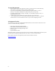
8 | LPR Printing Guide 8.1 | Installing a LPR Print Server on Windows XP and Windows 2000 NOTE • • These instructions assume that the printer has previously been installed on the computer. This is necessary to ensure that the printer drivers have been installed and are working correctly. Screen shots shown have been taken from Windows XP but differ only slightly from those used in Windows 2000. The instructions will highlight any important differences.
Step 2 – Select Local Printer Select Local Printer and make sure Automatically detect and install my Plug and Play printer is NOT selected. Press Next to move on. Step 3 – Create a new printer port This dialogue is critical to the operation of the Print Server. The Windows 2000 page looks very different but provides exactly the same options. Select Create a new port and select Standard TCP/IP Port from the Type of Port list. Press Next to launch the wizard that sets up the TCP/IP port.
Press Next again. Step 4 – Add Port The Add Port dialogue will appear: Enter the IP address of the Print Server in the Printer Name or IP Address field. The default address of your router should be 192.168.2.1 as shown on the dialogue above. The Port Name is automatically generated as the IP Address is entered but it can be changed to something more meaningful.
Step 5 – Custom Settings The Additional Port Information dialogue will appear. Select Custom and then press the Settings... button. The following dialogue will appear to allow you to set the protocol and Queue Name. The Queue should be entered as LP for a DB25 (parallel) printer or LPUSB for a USB printer. Check the LPR Byte Counting Press OK to continue.
This will return you to Additional Port Information dialogue. Press Next to display the following: Press Finish to close the wizard. Step 6 – Select Printer Driver A page will be displayed similar to that shown below which allows the selection of the correct driver for the printer.
Step 7 – Changing the Printer Name. When the correct driver has been selected or installed from disk, pressing Next will step through to the Printer Name screen. Selecting a memorable name for the printer is recommended. Press Next will step through the rest of the wizard. Step 8 - Finishing and printing a test page Other pages should be left as the values that appear automatically however it is strongly recommended that you print a Test Page.
8.2 | Installing the Print Server Monitor for Windows XP, 2000, NT NOTE • • These instructions assume that the printer has previously been installed on the computer. This is necessary to ensure that the printer drivers have been installed and are working correctly. Screen shots shown have been taken from Windows XP but differ only slightly from those used in Windows 2000. The instructions will highlight any important differences.
Adding a new printer Step 1 – Printers and Faxes Dialogue First display the Printers and Faxes dialogue by selecting Start->Control Panel->Printers and Faxes. Use Start->Settings->Control Panel->Printers and Faxes if you are using Windows 2000 or Windows XP in Classic mode. Next, in Windows XP, select Add a Printer from the left hand pane of the window or Right Click on the right hand pane and select Add Printer. In Windows 2000 you must double-click on the Add Printer icon.
Step 3 Select PTR mate port Step 4 – Select Printer Driver A page will be displayed similar to that shown below which allows the selection of the correct driver for the printer.
Step 5 – Changing the Printer Name. When the correct driver has been selected or installed from disk, pressing Next will step through to the Printer Name screen. Selecting a memorable name for the printer is recommended. Press Next will step through the rest of the wizard. Step 6: Choose appropriate printing method Go to Start->Settings->Printers and configure the PRT mate port for your USB or parallel printer. If the default IP address of the router (192.168.2.
8.3 | Installing the Printer Server on Windows 98/SE/ME NOTE • • • These instructions assume that the printer has previously been installed on the computer. This is necessary to ensure that the printer drivers have been installed and are working correctly. Screen shots shown have been taken from Windows Me.
Adding a new printer Step 1 - Display Printers Display the Printers dialogue by selecting Start->Settings->Control Panel->Printers An example of this window is shown below. Step 2 – Add Printer Click on Add Printer. This will load a wizard which will install a new printer on the computer. Press Next on the first screen and then the screen below will be displayed. Select Local printer and then press Next to move on.
Step 3 – Select printer Select the correct driver for the printer and then press Next to move on. Since the printer should have been previously installed the wizard will confirm that this is the correct driver. The existing driver should be kept and then Next should be pressed.
Step 4 – Port selection After installing the Printer Port Monitor at the start of this guide a PTR mate Port will now be available. Select the PTR mate Port and then press Configure Port... Step 5 – Configure Port The IP Address should be 192.168.2.1 (default) and the appropriate printer interface for your printer. Press OK to move on.
Step 6 – Printer Name Enter a memorable Printer name. Press Next to move on. Step 7 – Print a Test Page It is recommended that a test page is printed. Press Finish to complete the printer setup and this will also send the test page to the printer. NOTE – If the test page does not print restart your computer before reading the troubleshooting document.
8.4 | Installing an LPR Print Server on Linux NOTE – The screenshots shown below were produced on the KDE desktop of SuSE 9.1. Different Linux distributions will have different screens but the functionality will be similar. In summary, the information that you will have to provide is as follows Queue type: LPD Queue name: LP for DB25 (parallel) printer or LPUSB for USB printer Host: 192.168.2.1 NOTE – Printers MUST be installed by user ROOT so you must login as ROOT before starting the installation.
Step 3 – Select Queue type The following screen will appear: Select Remote LPD Queue as shown above then press Next to continue Step 4 – Enter Host and Queue information The IP of the Print Server is the Host (default=192.168.2.1). The Queue should be entered as LP for a DB25 (parallel) printer or LPUSB for a USB printer.
Step 5 – Select Printer Driver Select the correct printer driver for your printer. If the driver for you printer is not displayed, contact the printer manufacturer to obtain it. Press Next to continue Step 6 – Test the Printer It is recommended that you press Test to print a test page. Once the test page has printed press Next to step through the rest of the screens in the wizard.
Step 7 – Complete the Wizard The remaining screens in the wizard require no changes with the exception of the page shown below. You must enter a Name for the printer as this will be used to select the printer by applications and when the printer queue is displayed. Location and Description are optional but recommended. Press Next to display the last page of the wizard. Step 8 – Finished The last screen of the wizard gives a summary of the configuration that is about to be configured.
8.5 | Installing an LPR Print Server on Mac OS 9 NOTE – These instructions assume that the printer has previously been installed on the computer. Step 1 – Desktop Printer Utility Click on the desktop printer utility which is usually located in the Utilities folder within the Applications folder. Step 2 – Select Printer Type After a few seconds the following window will appear. Select Printer (LPR) and press OK.
Select the printer that is attached to the printer server from the list. Press Select to return to the previous window Now select Change... from within the LPR Printer Selection section Now enter the the IP address of the Printer Server as the Printer Address. This is normally 192.168.2.1 unless you have changed it something else. The Queue should be entered as LP for a DB25 (parallel) printer or LPUSB for a USB printer. Now press Verify.
8.6 | Installing an LPR Print Server on Mac OS X 10.3 NOTE – These instructions assume that the printer has previously been installed on the computer. Step 1 – Print Center Click on Printer Setup Utility which is located in the Utilities folder within the Applications folder. Step 2 – Add Printer After a few seconds the window shown below will appear. Select Add and the window shown below will be displayed.
The Queue should be entered as LP for a DB25 (parallel) printer or LPUSB for a USB printer Then select the printer that is attached to the printer server from the list. Now press Add to create the new printer. After pressing Add the Printer List screen will be displayed and should include the new printer. Step 4 – Test the printer The new printer should be tested by trying to print a page from the computer.
9 | Troubleshooting A. Verifying your connection to the router If you are unable to access the Router’s web-based administration pages, then you may not be properly connected or configured. To determine your TCP/IP configuration status please follow the steps below: 1. Click Start then choose Run. 2. Type cmd or command to open a DOS prompt. 3. In the DOS window, type ipconfig and verify the information that is displayed. 4.
F. I am having problems establishing a PPPoE xDSL WAN connection Some ISP’s require you to enter the domain name in addition to your username and password. For instance, for SBC Global, enter username@sbcglobal.net. For Ameritech users, enter username@ameritech.net. BellSouth users may need to enter username@bellsouth.net and Mindspring subscribers enter username@mindspring.com. Lastly, Earthlink subscribers should enter either username@earthlink.net or ELN/username@earthlink.net. G.
10 | Terminology 10BaseT - Physical Layer Specification for Twisted-Pair Ethernet using Unshielded Twisted Pair wire at 10Mbps. This is the most popular type of LAN cable used today because it is very cheap and easy to install. It uses RJ-45 connectors and has a cable length span of up to 100 meters. There are two versions, STP (Shielded Twisted Pair) which is more expensive and UTP (Unshielded Twisted Pair), the most popular cable. These cables come in 5 different categories.
DMZ - Allows a networked computer to be fully exposed to the Internet. This function is used when the special application sensing tunnel feature is insufficient to allow an application to function correctly. DNS - DNS stands for Domain Name System, which allows Internet host computers to have a domain name (such as www.smc.com) and one or more IP addresses (such as 192.34.45.8).
LAN - A communications network that serves users within a confined geographical area. It is made up of servers, workstations, a network operating system and a communications link. Servers are high-speed machines that hold programs and data shared by network users. The workstations (clients) are the users' personal computers, which perform stand-alone processing and access the network servers as required.
Packet Binary Convulational Code(tm) (PBCC) - A modulation technique developed by Texas Instruments Inc. (TI) that offers data rates of up to 22Mbit/s and is fully backward compatible with existing 802.11b wireless networks. PAP - This is a simple authentication protocol where the username and password data are both handled in a cleartext or unencrypted format.
11 | Technical Specifications Standards: IEEE 802.3 10Base-T Ethernet IEEE 802.3u 100Base-TX Fast Ethernet Hardware / Ports: LAN Port WAN Port USB Port Printer Port Input Power LEDs: Power WAN LAN (4 port) 4x RJ45, 10/100 Mbps with Auto-MDI/MDIX (BR14UP) 1x RJ45, 10/100 Mbps with Auto-MDI/MDIX 1 x USB Jack (type A), USB 1.
12 | COMPLIANCES FCC Interference Statement This equipment has been tested and found to comply with the limits for a Class B digital device pursuant to Part 15 of the FCC Rules. These limits are designed to provide reasonable protection against radio interference in a commercial environment. This equipment can generate, use and radiate radio frequency energy and, if not installed and used in accordance with the instructions in this manual, may cause harmful interference to radio communications.
Safety Compliance Wichtige Sicherheitshinweise (Germany) 1.Bitte lesen Sie diese Hinweise sorgfältig durch. 2.Heben Sie diese Anleitung für den späteren Gebrauch auf. 3.Vor jedem Reinigen ist das Gerät vom Stromnetz zu trennen. Verwenden Sie keine Flüssig- oder Aerosolreiniger. Ambesten eignet sich ein angefeuchtetes Tuch zur Reinigung. 4.Die Netzanschlußsteckdose soll nahe dem Gerät angebracht und leicht zugänglich sein. 5.Das Gerät ist vor Feuchtigkeit zu schützen. 6.
13 | LEGAL INFORMATION AND CONTACTS SMC's Limited Warranty Statement SMC Networks Europe ("SMC") warrants its products to be free from defects in workmanship and materials, under normal use and service, for the applicable warranty term. All SMC products carry a standard 2 year limited warranty from the date of purchase from SMC or its Authorized Reseller.
Full Installation Manual Full installation manuals are provided on the Installation CD-Rom. Manuals in other languages than those included on the CD-Rom are provided on www.smc.com (section support). Firmware and Drivers For latest driver, technical information and bug-fixes please visit www.smc.com (section support). Contact SMC Contact details for your relevant countries are available on www.smc.com.
FOR TECHNICAL SUPPORT, CALL: From U.S.A. and Canada (24 hours a day, 7 days a week) (800) SMC-4-YOU; Phn: (949) 679-8000; Fax: (949) 679-1481 From Europe : Contact details can be found on www.smc.com INTERNET E-mail address: techsupport@smc.com Driver updates: http://www.smc.com/index.cfm?action=tech_support_drivers_downloads World Wide Web: http://www.smc.com/ For Literature or Advertising Response, Call: U.S.A.