EZ Connect N ADSL2 BARRICADE ™ Draft 11nWireless WirelessAnnex USB2.
Contents 1 Introduction ............................................................................................................................................................. 1 1.1 Packing List............................................................................................................................................. 1 1.2 Safety Cautions........................................................................................................................................ 1 1.
.7.8 3.8 Other.............................................................................................................................................. 45 Admin.................................................................................................................................................... 48 3.8.1 Remote Access .............................................................................................................................. 48 3.8.2 Commit/Reboot ...................
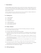
1 Introduction The SMC7904WBRA4 supports multiple line modes. It provides four 10/100 base-T Ethernet interfaces at the user end. The device provides high-speed ADSL broadband connection to the Internet or Intranet for high-end users, such as net bars and office users. The device provides high performance access to the Internet, downlink up to 24 Mbps and uplink up to 1 Mbps. The device supports WLAN access, as WLAN AP or WLAN router, to the Internet. It complies with IEEE 802.11, 802.
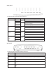
Front panel The following table describes the LEDs of the device. LED Status Color On Description The device is powered on and the initialization is normal. Green Off The device is powered off. Power On The device is initializing. Red Link Blinks The firmware is upgrading. On The Internet connection is normal. Blinks WLAN Blue Data is being transmitted on the Internet. Off The Internet connection is failed. On The WLAN connection is established.
Interface Function The button of the antenna. 1.4 System Requirements Recommended system requirements are as follows: A 10/100 base-T Ethernet card is installed on your PC A hub or Switch. (attached to several PCs through one of Ethernet interfaces on the device) Operating system: Windows 98SE, Windows 2000, Windows ME, Windows XP or Windows Vista Internet Explorer V5.0 or higher, Netscape V4.0 or higher, or firefox 1.5 or higher 1.
PPP session PAP and CHAP IP filter IP QoS Remote access control Line connection status test Remote management (telnet and HTTP) backup and restore of configuration file Ethernet interface supports crossover detection, auto-correction and polarity correction UPnP 4
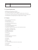
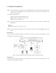
2 Hardware Installation Step 1 Connect the Line interface of the device and the Modem interface of the splitter through a telephone cable. Connect the phone to the Phone interface of the splitter through a cable. Connect the incoming line to the Line interface of the splitter. The splitter has three interfaces: – Line: Connect to a wall phone jack (RJ-11 jack) – Modem: Connect to the ADSL jack of the device – Phone: Connect to a telephone set.
Figure 2 (with a telephone set before the splitter) In the actual application, connection 1 is recommended. I Note: When connection 2 is used, the filter must be installed close to the telephone lines. Do not use the splitter instead of the filter. Installing a telephone directly before the splitter may lead to a failure of connection between the device and the office central, or cannot access into the Internet, or slow the connection speed.
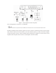
3 About the Web Configuration This chapter describes how to configure the router by using the Web-based configuration utility. 3.1 How to Access the Router The following is the detailed description of accesing the router for the first time. Step 1 Open the Internet Explorer (IE) browser and enter http://192.168.2.1. Step 2 In the LOGIN page that is displayed, enter the username and password. – The username and password of the super user are admin and smcadmin.
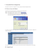
In the navigation bar, choose Setup Wizard. In the Setup Wizard page, you can configure the VPI/VCI number. The Setup Wizard page guides fast and accurate configuration of the Internet connection and other important parameters. The following sections describe these various configuration parameters. Whether you configure these parameters or use the default ones, click NEXT to enable your Internet connection.
The following table describes the parameters of this page. Field Description (Root) SSID SSID BroadCase Wireless Mode Channel Number After configuring the wireless settings, click NEXT. The page shown in the following figure appears. In this page, you can configure the ADSL settings. The following table describes the parameters and buttons in this page. Description Field Country Select the country in which you are in. Internet Service Provider Select your ISP.
You can choose LLC or VC-Mux. VPI VCI The virtual path between two points in an ATM network, and its valid value is from 0 to 255. The virtual channel between two points in an ATM network, ranging from 32 to 65535 (0 to 31 is reserved for local management of ATM traffic). Before you configure the protocol, you must select the country in which you are in and your ISP. PPPoE If the uplink equipment supports the PPPoE protocol, you can set the device to initiate the PPPoE dialup.
PPPoA If the uplink equipment supports the PPPoA encapsulation, you can set the device to initiate the PPPoA dialup. After finishing the settings, click NEXT. The page shown in the following figure appears.
If you ensure the configuration is correct, click FINISH. Then the configuration takes effect. You can check the configuration in the WAN page. Dynamic IP If the uplink equipment supports the Dynamic IP protocol, you can set the device to initiate the dynamic IP dialup. After finishing the settings, click NEXT. The page shown in the following figure appears.
If you ensure the configuration is correct, click FINISH. Then the configuration takes effect. You can check the configuration in the WAN page. Static IP If the uplink equipment supports the Static IP protocol, you can set the device to initiate the static IP dialup. After finishing the settings, click NEXT. The page shown in the following figure appears.
If you ensure the configuration is correct, click FINISH. Then the configuration takes effect. You can check the configuration in the WAN page. Bridge If the uplink equipment supports the Bridge protocol, you can set the device to initiate the bridge dialup. After finishing the settings, click NEXT. The page shown in the following figure appears.
If you ensure the configuration is correct, click FINISH. Then the configuration takes effect. You can check the configuration in the WAN page. 1483 Route If the uplink equipment supports the 1483 Route protocol, you can set the device to initiate the 1483 route dialup.
After finishing the settings, click NEXT. The page shown in the following figure appears. If you ensure the configuration is correct, click FINISH. Then the configuration takes effect. You can check the configuration in the WAN page.
I Note: After you select the country in which you are in and the correct ISP, the ADSL settings, such as protocol, connection type, VPI, and VCI appears. It is recommended to use the default values. 3.3 Status In the navigation bar, choose Status. In the Status page that is displayed contains: System, LAN, WLAN, WAN, Port Mapping, Statistic, and ARP Table. 3.3.1 System Choose Status > System.
3.3.3 WLAN Choose Status > WLAN. The page that is displayed shows some basic wirless LAN settings of the router. 3.3.4 WAN Choose Status > WAN. In the WAN page, you can view basic status of WAN, default gateway, DNS server. If you want to configure the WAN network, refer to the chapter3.6.1 WAN Interface.
3.3.5 Port Mapping Choose Status > Port Mapping. In the Port Mapping page, you can view the mapping relation and the status of port mapping. 3.3.6 Statistic Choose Status > Statistic. The Statistic page that is displayed contains Traffic Statistic and DSL Statistic. 3.3.6.1 Traffic Statistic Choose Traffic Statistic in the left pane. The page shown in the following figure appears. In this page, you can view the statistics of each network port.
3.3.6.2 DSL Statistic Choose DSL Statistic in the left pane. The page shown in the following figure appears. In this page, you can view the ADSL line statistics, downstream rate, upstream rate, and other information. 3.3.7 ARP Table Choose Status > ARP Table. In the ARP Table page, you can view the table which shows a list of learned MAC addresses. 3.4 LAN In the navigation bar, choose LAN. The LAN page that is displayed contains LAN Settings and DHCP Settings.
3.4.1 LAN Settings Choose LAN > LAN Settings. In the LAN Settings page, you can configure the LAN network. In this page, you can change IP address of the router. The default IP address is 192.168.2.1. This is the private IP address of the router. This is the address under which the router can be reached in the local network. It can be freely assigned from the block of available addresses. The following table describes the parameters and buttons of this page.
Select DHCP Proxy in the DHCP Server Setup page. The page shown in the following figure appears. The following table describes the parameters of this page. Field DHCP Proxy DHCP Server Address Description Select it, the router acts a surrogate DHCP Server and relays the DHCP requests and reponses between the remote server and the client. Enter the IP address of the actual, remote DHCP server. Select DHCP Server in the DHCP Server Setup page. The page shown in the following figure appears.
The following table describes the parameters in this page. Field Description If set to DHCP Server, the router can assign IP addresses, IP default gateway and DHCP Server DNS Servers to Windows95, Windows NT and other systems that support the DHCP client. IP Pool Range Show Client Max Lease Time It specifies the first and the last of contiguous IP address of the IP address pool. Click it, the Active DHCP Client Table page appears. It shows the assigned IP address of the clients.
Description Field the assigned IP addresses before the IP addresses change. Refresh Refresh the page. Close Close the page. Click MAC-based Assignment in the DHCP Server Setup page. The page shown in the following figure appears. In this page, you can assign the IP addresses on the LAN to the specific individual PCs based on their MAC address. The following table describes the parameters and buttons of this page. Field Description Host MAC Address Enter the MAC address of a PC on the LAN.
3.5.1 Basic Settings Choose WLAN > Basic Settings. The page shown in the following figure appears. In this page, you can configure the parameters for wireless LAN clients that may connect to your access point. The following table describes the parameters and buttons of this page. Field Disable Wireless Description LAN By default, the wireless LAN is enabled. Select it to disable the wireless LAN.
The following table describes the parameters and buttons of this page. Field Description Vap SSID The service set identification (SSID) is a unique name to identify the router in the wireless LAN Auth Type You can choose Open System, Shared Key, or Auto. If you select Open System, you can If you select Shared Key, you can If you select Auto, you can Apply Chnages Save the settings of this page. Undo Refresh this page. 3.5.2 Security Choose WLAN > Security.
The following table describes the parameters and buttons of this page. Field Description SSID Type Select the SSID. You can choose None, WEP, WPA (TKIP), WPA2 (AES), or WPA2 Mixed. Wired equivalent privacy (WEP) entrypts data frames before transmitting over the wireless network. Encryption Wi-Fi protected access (WPE) is a subset of the IEEE802.11i security specification draft. Key differences between WPA and WEP are user authentication and improved data encryption. It is available when you set to WEP.
The following table describes the parameters and buttons of this page. Field Description SSID TYPE Select the SSID. Key Length Select 64-bit or 128-bit to use data encryption. If you choose 64-bit, you can choose ASCII (5 characters) or Hex (10 characters). Key Format If you choose 128-bit, you can choose ASCII (13 characters) or Hex (26 characters). Default Tx Key Select the default encryption key. The Encryption keys are used to encrypt the data.
The following table describes the parameters of this page. Field Fragment Threshold Description This is the maximum data fragment size (between 256 and 2346bytes) that can be sent in the wireless network before the router fragments the packet into smaller data frames. Request to send (RTS) is designed to prevent collisions due to hidden node. A RTS defines the biggest size data frame you can send before a RTS handshake invoked. The RTS Threshold RTS threshold value is between 0 and 2347.
The following table describes the parameters and buttons of this page. Field Description You can choose Disable, Allow Listed, or Deny Listed. Select Allow Listed, only the clients whose MAC address is listed can access the Select Access Control router. Mode Select Deny Listed, the clients whose MAC address is listed are denied to access the router. Apply Changes MAC Addr Save the changes of selecting the access control mode.
The following table describes the fields of this screen. Label Description Enable WDS Select it to enable the WDS function. Otherwise, you can not configure the settings of this page. MAC Addr Enter the MAC address (in XX-XX-XX-XX-XX-XX format) of the AP. Comment Enter the comment to describe the AP of the MAC address. Apply Change Click it to add the MAC Addr with the Comment to Current WDS AP List. Reset Click it to refresh the MAC Addr and Comment.
The following table describes the parameters of this page. Field Description This table shows the existed PVCs. It shows the Interface name, channel mode, Current ATM VC Table VPI/VCI, encapsulation mode, local IP address, remote IP address and other information. The maximum item of this table is eight. Click it, the IP Interface-Modify page appears. You can modify the PVCs’ parameters. VPI VCI The virtual path between two points in an ATM network, ranging from 0 to 255.
Field Description If select Use DHCP, the router is a DHCP client, the WAN IP address is assigned by the remote DHCP server. Local IP Address It is the IP address of WAN interface which is provided by your ISP. Remote IP Address This is the gateway IP address which is provided by your ISP. Subnet Mask It is the subnet mask of the local IP address. Unnumbered Select this checkbox to enable IP Unnumbered function.
The following table describes the parameters and buttons of this page. Field Description 3.6.2 ADSL Settings Choose WAN > ADSL Settings. The page shown in the following figure appears. In this pae, you can select the DSL modulation. Mostly, you need to remain this factory default settings. The router supports these modulations: G.lite, G.Dmt, T1.413, ADSL2, ADSL2+, AnnexL, and AnnexM. The router negotiates the modulation modes with the DSLAM.
3.7 Advance In the navigation bar, choose Advance. The Advance page that is displayed contains DNS, Firewall, Virtual Server, Routing, IP QOS, Anti-DOs, Port Mapping, and Other. 3.7.1 DNS Choose Advance > DNS. The DNS page that is displayed contains DNS Server and DDNS. 3.7.1.1 DNS Server Choose DNS Server in the left pane. The page shown in the following figure appears. Domain name system (DNS) is an Internet service that translates the domain name into IP address.
The following table describes the parameters and buttons of this page. Field Obtain Description DNS Select it, the router accepts the first received DNS assignment from one of the PPPoA, Automatically PPPoE or MER enabled PVC(s) during the connection establishment. Set DNS Manually Select it, enter the primary and optional secondary DNS server IP addresses. Apply Changes Save the settings of this page. Reset Selected Refresh this page. 3.7.1.2 DDNS Choose DDNS in the left pane.
3.7.2 Firewall Choose Advance > Firewall. The Firewall page that is displayed contains IP/Port Fileter, MAC Filter, and URL Blocking. 3.7.2.1 IP/Port Filter Choose IP/Port Filter in the left pane. The page shown in the following figure appears. Entries in this table are used to restrict certain types of data packets through the gateway. These filters are helpful in securing or restricting your local network. Click Apply Changes to save the settings of this page.
Field 3.7.2.2 Description MAC Filter Choose MAC Filter in the left pane. The page shown in the following figure appears. Entries in this table are used to restrict certain types of data packets from your local network to Internet through the gateway. These filters are helpful in securing or restricting your local network. Click Apply Changes to save the settings of this page. Click Add Rule to add a new rule of the MAC filter. The following table describes the parameters and buttons of this page.
Field 3.7.2.3 Description URL Blocking Choose URL Blocking in the left pane. The page shown in the following figure appears. This page is used to block a fully qualified domain name (FQDN), such as tw.yahoo.comand and filtered keyword. You can add or delete FQDN and filtered keyword. The following table describes the parameters and buttons of this page. Field Description 3.7.3 Virtual Server Choose Advance > Virtual Server. The page shown in the following figure appears.
Click Add to add a virtual server. The page shown in the following figure appears. The following table describes the parameters and buttons of this page. Field 3.7.3.2 Description DMZ Settings Choose DMZ Settings in the left pane. The page shown in the following figure appears. A demilitarized zone is used to provide Internet services without sacrificing unauthorized access to its local private network.
3.7.4 Routing Choose Advance > Routing. The page shown in the following figure appears. The page that is displayed contains Static Route and RIP. 3.7.4.1 Static Route Choose Static Route in the left pane. The page shown in the following figure appears. In this page, you can configure the routing information. You can add or delete IP routes. The following table describes the parameters and buttons of this page. Field Description Click Show Routes. The table shown in the following figure appears.
3.7.4.2 RIP Choose RIP in the left pane. The page shown in the following figure appears. If you are using this device as a RIP-enabled router to communicate with others who is using the Routing Information Protocol (RIP), enable the RIP. This page is used to select the interfaces on your devices that use RIP, and the version of the protocol used. The following table describes the parameters and buttons of this page.
3.7.5 IP QoS Choose Advance > IP QOS. The page shown in the following figure appears. Entries in this table are used to assign the precedence for each incoming packet based on physical LAN port, TCP/UDP port number, and source/destination IP address/subnet masks. Click Add Rule, the page shown in the following figure appears. The following table describes the parameters and buttons of this page.
3.7.6 Anti-dos Choose Advance > Anti-Dos. The page shown in the following figure appears. Denial-of-service attack (DoS Attack) is a type of attack on a network that is designed to bring the network to its knees by flooding it with useless traffic. In this page, you can prevent DoS attacks. Click Apply Changes to save the settings of this page. 3.7.7 Port Mapping Choose Advance > Port Mapping. The page shown in the following figure appears.
3.7.8 Other Choose Advance > Other. In the Other page that is displayed contains IGMP Proxy, UPNP, Bridge, and IP PassThrough. 3.7.8.1 IGMP Proxy Choose IGMP Proxy in the left pane. The page shown in the following figure appears. IGMP proxy enables the system to issue IGMP host messages on behalf of hosts that the system discovered through standard IGMP interfaces. The system acts as a proxy for its hosts after you enable it.
Click Apply Changes to save the settings of this page. 3.7.8.2 UPNP Choose UPNP in the left pane. The page shown in the following figure appears. This page is used to configure UPnP. The system acts as a daemon after you enable it. Click Apply Changes to save the settings of this page. 3.7.8.3 Bridge Choose Bridge in the left pane. The page shown in the following figure appears. This page is used to configure the bridge parameters.
The following table describes the parameters and buttons of this page. Field Description Click Show MACs. The page shown in the following figure appears. This table shows a list of learned MAC addresses for this bridge. 3.7.8.4 IP PassThrough Choose IP Pass Through in the left pane. The page shown in the following figure appears. IP passthrough is also known as ZIPB or IP extension. In this page, you can enable and configure IP passthrough.
3.8 Admin In the navigation bar, choose Admin. The Admin page that is displayed contains Remote Access, Commit/Reboot, Password, Backup/Restore, Upgrade Fireware, Time Zone, System Log, SNMP, TR069, ACL, and Logout. 3.8.1 Remote Access Choose Admin > Remote Access. The page shown in the following figure appears. You can enable or disable the services which are used by the remote host.
The following table describes the parameters of this page. Field Description reset to default settings Select it to reset the router to the default settings. commit current settings Select it to save the current settings and reboot the router. Reboot Reboot the router. 3.8.3 Password Choose Admin > Password. The page shown in the following figure appears. In this page, you can change the password of the user, including admin and user.
Field Description user. New Password Enter the password to which you want to change the old password. Confirmed Password Enter the new password again. 3.8.4 Backup/Restore Choose Admin > Backup/Restore. The page shown in the following figure appears. In this page, you can backup the current settings to a file and restore the settings from the file which was saved previously. Note: Do not turn off your router or press the Reset button while these procedures are in progress.
The following table describes the parameters and buttons of this page. Field Description Select File Click Browse to select the firmware file. Upload Select the firmware file and click Upload to begin upgrading the firmware. Reset Click it to begin selecting the firmware file. 3.8.6 Time Zone Choose Admin > Time Zone. The page shown in the following figure appears. In this page, you can set the system time manually or get the system time from the time server.
Refresh Refresh the system shown in the page. You can choose Time Server or Manual. Select Time Server, the router gets the system time from the time server. Time Mode Select Manual, you should configure the system time manually. Enable SNTP Client Update Select it, you can choose the correct SNTP server which you want. SNTP Server Choose the SNTP server from the drop-down list box. Time Zone Select the time zone in which area you are. 3.8.7 System Log Choose Admin > System Log.
The following table describes the parameters and buttons of this page. Field Trap IP Address Community name (read-only) Community name (write-only) Description Enter the IP address of trap IP. The trap information is sent to the host. The network administrators must use this password to read the information of this router. The network administrators must use this password to configure the information of the router. 3.8.9 TR069 Choose Admin > TR069. The page shown in the following page appears.
The following table describes the parameters and buttons of this page. Field 3.8.10 Description ACL Choose Admin > ACL. The page shown in the following figure appears. In this page, you can configure the IP address in the access control list. If ACL is enabled, only the effective IP adresses in ACL can access the ADSL router.
Step 1 Select Enable and click take effect. Step 2 Configure the ACL. Step 3 Click take effect to take the configuration effect. I Note: If you select Enable in ACL Capability, ensure that your host IP address is in ACL list before it takes effect. 3.9 Diagnostic In the navigation bar, choose Diagnostic. The Diagnostic page that is displayed contains Ping, ATM Loopback, ADSL, and Diagnostic. 3.9.1 Ping Choose Diagnostic > Ping. The page shown in the following figure appears.
Field Description Host Address Enter the IP address. Go ! Click it to begin to Ping the host address. 3.9.2 ATM Loopback Choose Diagnostic > ATM Loopback. The page shown in the following figure appears. In this page, you can use VCC loopback function to check the connectivity of the VCC. 3.9.3 ADSL Choose Diagnostic > ADSL. The page shown in the following figure appears. It is used for ADSL tone diagnostics. Click Go! to begin ADSL tone diagnostics.
3.9.4 Diagnostic Choose Diagnostic. The page shown in the following figure appears. In this page, you can test the DSL connection. Click Run Diagnostic Test to begin testing.
Appendix A Questions & Answers This section describes common problems you may encounter and possible solutions to them. The Barricade can be easily monitored through panel indicators to identify problems. 1. Question: Why all LED indicators are off? Answer: Check the connection between the power adaptor and the power socket Check the power switch is on or not 2.
Click start -> run (input ping demands)-> Ping 192.168.2.1 (MODEM IP address). If cannot reach the modem, please check following configuration: The type of the network cable The connection between the modem and computer You computer’s TCP/IP configuration 6. Question: How to load the default setting after incorrect configuration? Answer: Press “reset” button 5s-10s to load the default configuration. The modem’s default IP address: 192.168.2.1/255.255.255.
Appendix B Technical Specifications External Connectors 1 push power switch 1 DC power jack 1 factory reset button 4 LAN 10/100M Auto MDI/MDIX RJ45 ports 1 WAN RJ11 DSL port Protocol Feature Bridging/Routing RFC 1483 Bridge IEEE 802.
Ethernet Feature Fully compliant with IEEE802.3/802.3u auto-negotiation function Support 10base-T, 100base-TX Support half duplex, full duplex Support back pressure flow control for half duplex, IEEE802.
Appendix C GPL Anouncement GNU GENERAL PUBLIC LICENSE Version 2, June 1991 Copyright (C) 1989, 1991 Free Software Foundation, Inc., 51 Franklin Street, Fifth Floor, Boston, MA 02110-1301 USA Everyone is permitted to copy and distribute verbatim copies of this license document, but changing it is not allowed. Preamble The licenses for most software are designed to take away your freedom to share and change it.
The precise terms and conditions for copying, distribution and modification follow. GNU GENERAL PUBLIC LICENSE TERMS AND CONDITIONS FOR COPYING, DISTRIBUTION AND MODIFICATION 0. This License applies to any program or other work which contains a notice placed by the copyright holder saying it may be distributed under the terms of this General Public License.
These requirements apply to the modified work as a whole. If identifiable sections of that work are not derived from the Program, and can be reasonably considered independent and separate works in themselves, then this License, and its terms, do not apply to those sections when you distribute them as separate works.
this License. Any attempt otherwise to copy, modify, sublicense or distribute the Program is void, and will automatically terminate your rights under this License. However, parties who have received copies, or rights, from you under this License will not have their licenses terminated so long as such parties remain in full compliance. 5. You are not required to accept this License, since you have not signed it.
9. The Free Software Foundation may publish revised and/or new versions of the General Public License from time to time. Such new versions will be similar in spirit to the present version, but may differ in detail to address new problems or concerns. Each version is given a distinguishing version number.
REPAIR OR CORRECTION. 12.
The hypothetical commands `show w' and `show c' should show the appropriate parts of the General Public License. Of course, the commands you use may be called something other than `show w' and `show c'; they could even be mouse-clicks or menu items--whatever suits your program. You should also get your employer (if you work as a programmer) or your school, if any, to sign a "copyright disclaimer" for the program, if necessary. Here is a sample; alter the names: Yoyodyne, Inc.
SMC7904WBRA4