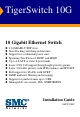
TigerSwitch 10G 10 Gigabit Ethernet Switch ◆ ◆ ◆ ◆ ◆ ◆ ◆ ◆ ◆ ◆ ◆ 8 10GBASE-T XFP slots Non-blocking switching architecture Support for a redundant power unit Spanning Tree Protocol, RSTP, and MSTP Up to 4 LACP or static 8-port trunks Layer 2/3/4 CoS support through eight priority queues Layer 3/4 traffic priority with IP Precedence and IP DSCP Full support for VLANs with GVRP IGMP multicast filtering and snooping Support for jumbo frames up to 9 KB Manageable via console, Web, SNMP/RMON Installation Guid
TigerSwitch 10G Installation Guide From SMC’s Tiger line of feature-rich workgroup LAN solutions 38 Tesla Irvine, CA 92618 Phone: (949) 679-8000 January 2005 Pub.
Information furnished by SMC Networks, Inc. (SMC) is believed to be accurate and reliable. However, no responsibility is assumed by SMC for its use, nor for any infringements of patents or other rights of third parties which may result from its use. No license is granted by implication or otherwise under any patent or patent rights of SMC. SMC reserves the right to change specifications at any time without notice. Copyright © 2005 by SMC Networks, Inc. 38 Tesla Irvine, CA 92618 All rights reserved.
LIMITED WARRANTY Limited Warranty Statement: SMC Networks, Inc. (“SMC”) warrants its products to be free from defects in workmanship and materials, under normal use and service, for the applicable warranty term. All SMC products carry a standard 90-day limited warranty from the date of purchase from SMC or its Authorized Reseller. SMC may, at its own discretion, repair or replace any product not operating as warranted with a similar or functionally equivalent product, during the applicable warranty term.
WARRANTIES EXCLUSIVE: IF AN SMC PRODUCT DOES NOT OPERATE AS WARRANTED ABOVE, CUSTOMER’S SOLE REMEDY SHALL BE REPAIR OR REPLACEMENT OF THE PRODUCT IN QUESTION, AT SMC’S OPTION. THE FOREGOING WARRANTIES AND REMEDIES ARE EXCLUSIVE AND ARE IN LIEU OF ALL OTHER WARRANTIES OR CONDITIONS, EXPRESS OR IMPLIED, EITHER IN FACT OR BY OPERATION OF LAW, STATUTORY OR OTHERWISE, INCLUDING WARRANTIES OR CONDITIONS OF MERCHANTABILITY AND FITNESS FOR A PARTICULAR PURPOSE.
COMPLIANCES FCC - Class A This equipment generates, uses, and can radiate radio frequency energy and, if not installed and used in accordance with the instruction manual, may cause interference to radio communications. It has been tested and found to comply with the limits for a Class A computing device pursuant to Subpart B of Part 15 of FCC Rules, which are designed to provide reasonable protection against such interference when operated in a commercial environment.
COMPLIANCES CE Mark Declaration of Conformance for EMI and Safety (EEC) SMC contact for these products in Europe is: SMC Networks Europe, Edificio Conata II, Calle Fructuós Gelabert 6-8, 2o, 4a, 08970 - Sant Joan Despí, Barcelona, Spain.
COMPLIANCES Australia AS/NZS 3548 (1995) - Class A SMC contact for products in Australia is: SMC Communications Pty. Ltd. Suite 18, 12 Tryon Road, Lindfield NSW2070, Phone: 61-2-94160437 Fax: 61-2-94160474 Safety Compliance Warning: Fiber Optic Port Safety CLASS I LASER DEVICE When using a fiber optic port, never look at the transmit laser while it is powered on. Also, never look directly at the fiber TX port and fiber cable ends when they are powered on.
COMPLIANCES • This unit operates under SELV (Safety Extra Low Voltage) conditions according to IEC 60950. The conditions are only maintained if the equipment to which it is connected also operates under SELV conditions. France and Peru only This unit cannot be powered from IT† supplies. If your supplies are of IT type, this unit must be powered by 230 V (2P+T) via an isolation transformer ratio 1:1, with the secondary connection point labelled Neutral, connected directly to earth (ground).
COMPLIANCES Veuillez lire à fond l'information de la sécurité suivante avant d'installer le Switch: AVERTISSEMENT: L’installation et la dépose de ce groupe doivent être confiés à un personnel qualifié. • Ne branchez pas votre appareil sur une prise secteur (alimentation électrique) lorsqu'il n'y a pas de connexion de mise à la terre (mise à la masse). • Vous devez raccorder ce groupe à une sortie mise à la terre (mise à la masse) afin de respecter les normes internationales de sécurité.
COMPLIANCES Cordon électrique - Il doit être agréé dans le pays d’utilisation Suisse: La prise mâle d’alimentation doit respecter la norme SEV/ASE 1011. Europe La prise secteur doit être conforme aux normes CEE 7/7 (“SCHUKO”) LE cordon secteur doit porter la mention ou et doit être de type HO3VVF3GO.75 (minimum).
COMPLIANCES Warnings and Cautionary Messages Warning: This product does not contain any serviceable user parts. Warning: Installation and removal of the unit must be carried out by qualified personnel only. Warning: When connecting this device to a power outlet, connect the field ground lead on the tri-pole power plug to a valid earth ground line to prevent electrical hazards. Warning: This switch uses lasers to transmit signals over fiber optic cable.
COMPLIANCES End of Product Life Span This product is manufactured in such a way as to allow for the recovery and disposal of all included electrical components once the product has reached the end of its life. Manufacturing Materials There are no hazardous nor ozone-depleting materials in this product. Documentation All printed documentation for this product uses biodegradable paper that originates from sustained and managed forests. The inks used in the printing process are non-toxic.
TABLE OF CONTENTS 1 About the TigerSwitch 10G . . . . . . . . . . . . . . . . . . . . . . .1-1 Overview . . . . . . . . . . . . . . . . . . . . . . . . . . . . . . . . . . . . . . . . . . . . . . . . . . . Switch Architecture . . . . . . . . . . . . . . . . . . . . . . . . . . . . . . . . . . . . . Network Management Options . . . . . . . . . . . . . . . . . . . . . . . . . . . . Description of Hardware . . . . . . . . . . . . . . . . . . . . . . . . . . . . . . . . . . . . . . . 10GBASE Slots . . . . . .
TABLE OF CONTENTS Wiring Map for Serial Cable . . . . . . . . . . . . . . . . . . . . . . . . . . . . . . 3-10 4 Making Network Connections . . . . . . . . . . . . . . . . . . . . 4-1 Connecting Network Devices . . . . . . . . . . . . . . . . . . . . . . . . . . . . . . . . . . . 4-1 Connecting to the Management Port . . . . . . . . . . . . . . . . . . . . . . . . . . . . . 4-1 Cabling Guidelines . . . . . . . . . . . . . . . . . . . . . . . . . . . . . . . . . . . . . .
TABLE OF CONTENTS APPENDICES: A Troubleshooting . . . . . . . . . . . . . . . . . . . . . . . . . . . . . .A-1 Diagnosing Switch Indicators . . . . . . . . . . . . . . . . . . . . . . . . . . . . . . . . . A-1 Diagnosing Power Problems with the LEDs . . . . . . . . . . . . . . . A-2 Power and Cooling Problems . . . . . . . . . . . . . . . . . . . . . . . . . . . . . . . . . A-2 Installation . . . . . . . . . . . . . . . . . . . . . . . . . . . . . . . . . . . . . . . . . . . . . . . . A-2 In-Band Access .
TABLES Table 1-1 Table 1-2 Table 1-3 Table 3-1 Table 4-1 Table 4-2 Table 4-3 Table 4-4 Table A-1 Table A-2 Table B-1 Table D-1 Approved XFP Transceivers . . . . . . . . . . . . . . . . . . . . . . . . . 1-3 Port Status LEDs . . . . . . . . . . . . . . . . . . . . . . . . . . . . . . . . . . 1-5 System Status LEDs . . . . . . . . . . . . . . . . . . . . . . . . . . . . . . . . 1-6 Serial Cable Wiring . . . . . . . . . . . . . . . . . . . . . . . . . . . . . . . .
FIGURES Figure 1-1 Figure 1-2 Figure 1-3 Figure 1-4 Figure 2-1 Figure 2-2 Figure 2-3 Figure 3-1 Figure 3-2 Figure 3-3 Figure 3-4 Figure 3-5 Figure 3-6 Figure 3-7 Figure 4-1 Figure 4-2 Figure 4-3 Figure B-1 Figure B-2 Figure B-3 Front and Rear Panels . . . . . . . . . . . . . . . . . . . . . . . . . . . . 1-1 Port LEDs . . . . . . . . . . . . . . . . . . . . . . . . . . . . . . . . . . . . . 1-4 System LEDs . . . . . . . . . . . . . . . . . . . . . . . . . . . . . . . . . . . 1-6 Power Supply Receptacle . .
FIGURES xvi
CHAPTER 1 ABOUT THE TIGERSWITCH 10G Overview The SMC8708L2 is a 10 Gigabit Ethernet switch with 8 10GBASE XFP slots*, and 1 10/100BASE-TX RJ-45 management port. The switch also includes an SNMP-based management agent, which provides both in-band and out-of-band access for managing the switch. This switch provides a broad range of powerful features for Layer 2 switching, delivering reliability and consistent performance for your network traffic.
ABOUT THE TIGERSWITCH 10G Switch Architecture The SMC8708L2 switch employs a wire-speed, non-blocking switching fabric. This permits simultaneous wire-speed transport of multiple packets at low latency on all ports. The switch also features full-duplex capability on all ports, which effectively doubles the bandwidth of each connection. This switch uses store-and-forward switching to ensure maximum data integrity.
DESCRIPTION OF HARDWARE Table 1-1 Approved XFP Transceivers Vendor Part Number 10 GbE Optic Maximum Distance Fiber Type Intel TXN18107 LR 10 km SMF JDS uniphase 64P0194 SR 300 m MMF Bookham IGF-17311 LR 10 km SMF Finisar FTRX-1411-3 LR 10 km SMF Agilent HFCT-711XPD LR 10 km SMF Picolight PL-XXL-SC-S45-0A SR 300 m MMF JDS Uniphase JXPR01SW04301 SR 300 m MMF JDS Uniphase JSPR01LW04301_LR LR 10 km SMF Management Port (RJ-45) The SMC8708L2 contains one 10/100BASE-TX
ABOUT THE TIGERSWITCH 10G Port and System Status LEDs The SMC8708L2 includes a display panel for key system and port indications that simplify installation and network troubleshooting. The LEDs, which are located on the front panel for easy viewing, are described in the following figures and tables..
DESCRIPTION OF HARDWARE Table 1-2 Port Status LEDs LED Condition Status 10 Gigabit Ethernet Ports (Ports 1-8) Link/Act On/Flashing Green Port has established a valid 10 Gbps network connection. Flashing indicates activity. Yellow/Green The port has been administratively disabled. Alternate XFP Module Off There is no valid link on the port. Green There is an XFP transceiver present in the slot. Off There is no transceiver in the slot.
ABOUT THE TIGERSWITCH 10G System LEDs Figure 1-3 System LEDs Table 1-3 System Status LEDs LED Condition Status PWR On Green The unit’s internal power supply is operating normally. On Yellow The unit’s internal power supply has failed. Off The unit has no power connected or has failed. On Green The redundant power supply is operating normally. On Yellow The redundant power supply is plugged in but faulty, such as a thermal or fan failure. Off No redundant power supply is connected.
DESCRIPTION OF HARDWARE Table 1-3 System Status LEDs (Continued) LED Condition Status Diag Flashing Green The system diagnostic test is in progress. On Green The system diagnostic test has completed successfully. On Yellow The system diagnostic test has detected a fault. Yellow/Green Alternating There has been a fan fault or the unit has overheated.
ABOUT THE TIGERSWITCH 10G Features and Benefits Connectivity • 8 10GBASE-T XFP slots for 10 Gbps Ethernet connections – supports 10GBASE-SR and 10GBASE-LR XFP transceivers • One 100BASE-TX management port - Auto-negotiation enable the RJ-45 management port to automatically select the optimum communication mode (half or full duplex) if this feature is supported by the attached device; otherwise the port can be configured manually - RJ-45 port supports auto MDI/MDI-X pinout selection - Unshielded (UTP) ca
FEATURES AND BENEFITS Management • “At-a-glance” LEDs for easy troubleshooting • Network management agent: - Manages switch in-band or out-of-band - Supports console, Telnet, SSH, SNMP v1/v2c/v3, RMON 4 groups and web-based interface 1-9
ABOUT THE TIGERSWITCH 10G 1-10
CHAPTER 2 NETWORK PLANNING Introduction to Switching A network switch allows simultaneous transmission of multiple packets via non-crossbar switching. This means that it can partition a network more efficiently than bridges or routers. The switch has, therefore, been recognized as one of the most important building blocks for today’s networking technology.
NETWORK PLANNING Application Examples The TigerSwitch 10G is not only designed to segment your network, but also to provide a wide range of options in setting up network connections. Some typical applications are described below. Network Aggregation Plan With 8 parallel bridging ports (i.e., 8 distinct collision domains), the TigerSwitch 10G can collapse a complex network down into a single efficient bridged node, increasing overall bandwidth and throughput.
APPLICATION EXAMPLES Remote Connections with Fiber Cable Fiber optic technology allows for longer cabling than any other media type. A 10GBASE-SR (MMF) link can connect to a site up to 300 meters away, and a 10GBASE-LR (SMF) link can connect to a remote site up to 10 km away. This allows a 10 Gigabit Ethernet Switch to serve as a collapsed backbone, providing direct connectivity for a widespread LAN.
NETWORK PLANNING Making VLAN Connections This switch supports VLANs which can be used to organize any group of network nodes into separate broadcast domains. VLANs confine broadcast traffic to the originating group, and can eliminate broadcast storms in large networks. This provides a more secure and cleaner network environment. VLANs can be based on untagged port groups, or traffic can be explicitly tagged to identify the VLAN group to which it belongs.
APPLICATION NOTES Application Notes 1. Full-duplex operation only applies to point-to-point access (such as when a switch is attached to a workstation, server or another switch). When the switch is connected to a hub, both devices must operate in half-duplex mode. 2. For network applications that require routing, you can attach this switch to a router or WAN gateway. 3. As a general rule the length of fiber optic cable for a single switched link should not exceed: • 10GBASE-SR: 300 m (984.
NETWORK PLANNING 2-6
CHAPTER 3 INSTALLING THE SWITCH Selecting a Site TigerSwitch 10G units can be mounted in a standard 19-inch equipment rack or on a flat surface. Be sure to follow the guidelines below when choosing a location. • The site should: - be at the center of all the devices you want to link and near a power outlet.
INSTALLING THE SWITCH Ethernet Cabling To ensure proper operation when connecting to the management port, make sure the current cable is suitable for 10BASE-T or 100BASE-TX operation. Check the following criteria against the current installation of your network: • Cable type: Unshielded twisted pair (UTP) or shielded twisted pair (STP) cables with RJ-45 connectors; Category 3 or better for 10BASE-T, or Category 5 or better for 100BASE-TX.
EQUIPMENT CHECKLIST Equipment Checklist After unpacking this switch, check the contents to be sure you have received all the components. Then, before beginning the installation, be sure you have all other necessary installation equipment.
INSTALLING THE SWITCH Mounting This switch can be mounted in a standard 19-inch equipment rack or on a desktop or shelf. Mounting instructions for each type of site follow. Rack Mounting Before rack mounting the switch, pay particular attention to the following factors: • Temperature: Since the temperature within a rack assembly may be higher than the ambient room temperature, check that the rack-environment temperature is within the specified operating temperature range. (See page C-2.
MOUNTING To rack-mount devices: 1. Attach the brackets to the device using the screws provided in the Bracket Mounting Kit. Figure 3-2 Attaching the Brackets 2. Mount the device in the rack, using four rack-mounting screws (not provided).
INSTALLING THE SWITCH 3. If installing a single switch only, turn to “Connecting to a Power Source” at the end of this chapter. 4. If installing multiple switches, mount them in the rack, one below the other, in any order. 5. If also installing an RPS, mount it in the rack below the other devices. Montage (Rack Mounting Instructions - German) SMC8708L2 Switch-Einheiten können an ein standardmäßiges 19-Zoll Einrichtungsrack, einen Arbeitstisch oder ein Regal montiert werden.
MOUNTING Desktop or Shelf Mounting 1. Attach the four adhesive feet to the bottom of the first switch. Figure 3-4 Attaching the Adhesive Feet 2. Set the device on a flat surface near an AC power source, making sure there are at least two inches of space on all sides for proper air flow. 3. If installing a single switch only, go to “Connecting to a Power Source” at the end of this chapter. 4. If installing multiple switches, attach four adhesive feet to each one.
INSTALLING THE SWITCH Installing an XFP Transceiver Figure 3-5 Installing an XFP Transceiver The XFP slots support the following XFP transceivers: • 10GBASE-SR • 10GBASE-LR To install an XFP transceiver, do the following: 1. Consider network and cabling requirements to select an appropriate XFP transceiver type. 2. Insert the transceiver with the connector facing outward and the slot connector facing down. Note that XFP transceivers are keyed so they can only be installed in one orientation. 3.
CONNECTING TO A POWER SOURCE Connecting to a Power Source To connect a switch to a power source: 1. Insert the power cable plug directly into the AC receptacle located at the back of the switch. 100-240V~ 50-60Hz 2A Figure 3-6 Power Receptacle 2. Plug the other end of the cable into a grounded, 3-pin, AC power source. Note: For International use, you may need to change the AC line cord. You must use a line cord set that has been approved for the receptacle type in your country. 3.
INSTALLING THE SWITCH Connecting to the Console Port The DB-9 serial port on the switch’s rear panel is used to connect to the switch for out-of-band console configuration. The command-line-driven configuration program can be accessed from a terminal or a PC running a terminal emulation program. The pin assignments used to connect to the serial port are provided in the following table.
CHAPTER 4 MAKING NETWORK CONNECTIONS Connecting Network Devices The TigerSwitch 10G is designed to interconnect multiple segments (or collision domains). It includes a 100BASE-TX port for management access, and 8 XFP ports for high-speed connections to your data network. XFP transceivers can be connected to any network device that supports the required 10 Gigabit Ethernet media type, such as network cards in PCs and servers, as well as to switches, routers, or remote devices.
MAKING NETWORK CONNECTIONS Caution: Do not plug a phone jack connector into an RJ-45 port. This will damage the switch. Use only twisted-pair cables with RJ-45 connectors that conform to FCC standards. Connecting Devices to the Management Port 1. Attach one end of a twisted-pair cable segment to the device’s RJ-45 connector. Figure 4-1 Making Twisted-Pair Connections 2.
CONNECTING TO THE MANAGEMENT PORT Network Wiring Connections Today, the punch-down block is an integral part of many of the newer equipment racks. It is actually part of the patch panel. Instructions for making connections in the wiring closet with this type of equipment follows. 1. Attach one end of a patch cable to the switch’s management port, and the other end to the patch panel. 2.
MAKING NETWORK CONNECTIONS Fiber Optic XFP Devices A 10 Gigabit XFP transceiver (10GBASE-SR or 10GBASE-LR) can be used for a backbone connection between switches, or for connecting to a high-speed server. For information on installing fiber optic XFP transceivers, refer to the following description. Each single-mode fiber port requires 9/125 micron single-mode fiber optic cable with an LC connector at both ends.
FIBER OPTIC XFP DEVICES 2. Check that the fiber terminators are clean. You can clean the cable plugs by wiping them gently with a clean tissue or cotton ball moistened with a little ethanol. Dirty fiber terminators on fiber optic cables will impair the quality of the light transmitted through the cable and lead to degraded performance on the port. 3. Connect one end of the cable to the LC port on the transceiver and the other end to the LC port on the other device.
MAKING NETWORK CONNECTIONS Connectivity Rules 10 Gigabit Ethernet Collision Domain Table 4-1 Maximum 10GBASE-SR 10 Gigabit Ethernet Cable Length Fiber Diameter Fiber Bandwidth Maximum Cable Length Connector 62.5/125 micron multimode fiber 160 MHz/km 2-26 m (6.56-85.3 ft.) LC 62.5/125 micron multimode fiber 200 MHz/km 2-33 m (6.56-108.26 ft.) LC 50/125 micron multimode fiber 400 MHz/km 2-66 m (6.56-216.54 ft.) LC 50/125 micron multimode fiber 500 MHz/km 2-82 m (6.56-269 ft.
CABLE LABELING AND CONNECTION RECORDS 10 Mbps Ethernet Collision Domain Table 4-4 Maximum Ethernet Cable Length Type Cable Type Maximum Cable Length Connect or 10BASE-T Twisted Pair, Category 3 or better 100-ohm UTP 100 m (328 ft) RJ-45 Cable Labeling and Connection Records When planning a network installation, it is essential to label the opposing ends of cables and to record where each cable is connected.
MAKING NETWORK CONNECTIONS 4-8
APPENDIX A TROUBLESHOOTING Diagnosing Switch Indicators Table A-1 Troubleshooting Chart Symptom Action PWR LED is Off • Check connections between the switch, the power cord, and the wall outlet. • Contact SMC Technical Support. • Internal power supply has failed. Contact your local dealer for assistance. PWR LED is Yellow Diag LED is Yellow Link LED is Off • Power cycle the switch to try and clear the condition. • If the condition does not clear, contact your local dealer for assistance.
TROUBLESHOOTING Diagnosing Power Problems with the LEDs The PWR and RPS LEDs work in combination to indicate power status as follows. Table A-2 Power/RPS LEDs PWR LED RPS LED Status Green Yellow Internal power functioning normally; RPS plugged in but faulty, such as a thermal or fan failure. Green Off Internal power functioning normally; RPS not plugged in. Yellow Green Internal power faulty; RPS delivering power. Off Off Both internal power and RPS unplugged or not functioning.
IN-BAND ACCESS In-Band Access You can access the management agent in the switch from anywhere within the attached network using Telnet, a Web browser, or other network management software tools. However, you must first configure the switch with a valid IP address, subnet mask, and default gateway. If you have trouble establishing a link to the management agent, check to see if you have a valid network connection. Then verify that you entered the correct IP address.
TROUBLESHOOTING A-4
APPENDIX B CABLES Twisted-Pair Cable and Pin Assignments For 10BASE-T/100BASE-TX connections to the management port, a twisted-pair cable must have two pairs of wires. Each wire pair is identified by two different colors. For example, one wire might be green and the other, green with white stripes. Also, an RJ-45 connector must be attached to both ends of the cable. Caution: Each wire pair must be attached to the RJ-45 connectors in a specific orientation.
CABLES 10BASE-T/100BASE-TX Pin Assignments Use unshielded twisted-pair (UTP) or shielded twisted-pair (STP) cable for RJ-45 connections: 100-ohm Category 3 or better cable for 10 Mbps connections, or 100-ohm Category 5 or better cable for 100 Mbps connections. Also be sure that the length of any twisted-pair connection does not exceed 100 meters (328 feet).
TWISTED-PAIR CABLE AND PIN ASSIGNMENTS EIA/TIA 568B RJ-45 Wiring Standard 10/100BASE-TX Straight-through Cable White/Orange Stripe Orange 1 2 3 4 5 6 7 8 End A White/Green Stripe Blue White/Blue Stripe Green White/Brown Stripe 1 2 3 4 5 6 7 8 End B Brown Figure B-2 Straight-through Wiring Crossover Wiring If the twisted-pair cable is to join two ports and either both ports are labeled with an “X” (indicating MDI-X) or neither port is labeled with an “X” (which indicates MDI), a crossover must be impl
CABLES Fiber Standards The current TIA (Telecommunications Industry Association) 568-A specification on optical fiber cabling consists of one recognized cable type for horizontal subsytems and two cable types for backbone subsystems. Horizontal 62.5/125 micron multimode (two fibers per outlet). Backbone 62.5/125 micron multimode or single mode. TIA 568-B will allow the use of 50/125 micron multimode optical fiber in both the horizontal and backbone in addition to the types listed above.
APPENDIX C SPECIFICATIONS Physical Characteristics Ports 8 XFP slots, with auto-negotiation 1 10/100BASE-TX, with auto-negotiation Network Interface XFP Slots: 10GBASE-SR and 10GBASE-LR approved XFP transceivers Management Port: RJ-45 connector, auto MDI/X 10BASE-T: RJ-45 (100-ohm, UTP cable; Category 3 or better) 100BASE-TX: RJ-45 (100-ohm, UTP cable; Category 5 or better) *Maximum Cable Length - 100 m (328 ft) Buffer Architecture 8 Mbytes Aggregate Bandwidth 160 Gbps Switching Database 16K MAC address ent
SPECIFICATIONS Size 44.0 x 41.0 x 4.3 cm (17.32 x 16.14 x 1.69 in.) Temperature Operating: 0 to 50 °C (32 to 122 °F) Storage: -40 to 70 °C (-40 to 158 °F) Humidity Operating: 5% to 95% (non-condensing) AC Input 100 to 240 V, 50-60 Hz, 2A Power Supply Internal, auto-ranging transformer: 100 to 240 VAC, 50 to 60 Hz External, supports connection for redundant power supply Power Consumption 150 Watts maximum Maximum Current 2.00 A @ 100 VAC 1.
STANDARDS Out-of-Band Management RS-232 DB-9 console port Software Loading TFTP in-band, or XModem out-of-band Standards IEEE 802.3-2002 Ethernet, Fast Ethernet, Gigabit Ethernet IEEE 802.3ae 10 Gigabit Ethernet IEEE 802.1D Spanning Tree Protocol IEEE 802.1w Rapid Spanning Tree Protocol IEEE 802.
SPECIFICATIONS Warranty Limited Lifetime C-4
APPENDIX D ORDERING INFORMATION Table D-1 TigerSwitch 10G Products and Accessories Product Number Description SMC8708L2 8-port 10G managed Layer 2 switch SMCRPU600W* Redundant power unit with cables, supports one device * Also available in models for Continental Europe and the UK.
ORDERING INFORMATION D-2
GLOSSARY 10BASE-T IEEE 802.3 specification for 10 Mbps Ethernet over two pairs of Category 3 or better UTP cable. 100BASE-TX IEEE 802.3u specification for 100 Mbps Fast Ethernet over two pairs of Category 5 or better UTP cable. 10GBASE-SR IEEE 802.3ae specification for 10 Gigabit Ethernet over two strands of 50/125 micron core multimode fiber cable. 10GBASE-LR IEEE 802.3ae specification for 10 Gigabit Ethernet over two strands of 9/125 micron core single-mode fiber cable.
GLOSSARY Collision A condition in which packets transmitted over the cable interfere with each other. Their interference makes both signals unintelligible. Collision Domain Single CSMA/CD LAN segment. CSMA/CD CSMA/CD (Carrier Sense Multiple Access/Collision Detect) is the communication method employed by Ethernet, Fast Ethernet, or Gigabit Ethernet. End Station A workstation, server, or other device that does not forward traffic.
GLOSSARY IEEE 802.3 Defines carrier sense multiple access with collision detection (CSMA/CD) access method and physical layer specifications. IEEE 802.3ab Defines CSMA/CD access method and physical layer specifications for 1000BASE-T Gigabit Ethernet. (Now incorporated in IEEE 802.3-2002.) IEEE 802.3ae Defines the physical layer specifications for 10 Gigabit Ethernet over fiber. IEEE 802.3ak Defines the physical layer specifications for 10 Gigabit Ethernet over coaxial cable. IEEE 802.
GLOSSARY Media Access Control (MAC) A portion of the networking protocol that governs access to the transmission medium, facilitating the exchange of data between network nodes. MIB An acronym for Management Information Base. It is a set of database objects that contains information about the device. Modal Bandwidth Bandwidth for multimode fiber is referred to as modal bandwidth because it varies with the modal field (or core diameter) of the fiber.
GLOSSARY Transmission Control Protocol/Internet Protocol (TCP/IP) Protocol suite that includes TCP as the primary transport protocol, and IP as the network layer protocol. UTP Unshielded twisted-pair cable. Virtual LAN (VLAN) A Virtual LAN is a collection of network nodes that share the same collision domain regardless of their physical location or connection point in the network.
GLOSSARY Glossary-6
INDEX Numerics 10 Gbps connectivity rules 4-6 10 Mbps connectivity rules 4-7 100 Mbps connectivity rules 4-6 1000BASE-LR fiber cable lengths 4-6 1000BASE-SR fiber cable lengths 4-6 100BASE-TX cable lengths 4-6 pin assignments B-2 ports 1-3 10BASE-T cable lengths 4-7 pin assignments B-2 10GBASE slots 1-2 A accessories, ordering D-1 adhesive feet, attaching 3-7 air flow requirements 3-1 applications network aggregation 2-2 remote connections with fiber 2-3 VLAN connections 2-4 compliances EMC C-3 safety C-3
INDEX G M grounding for racks 3-4 management agent 1-2 features 1-9, C-2, C-3 out-of-band 1-2 SNMP 1-2 web-based 1-2 mounting the switch in a rack 3-4 on a desktop or shelf 3-7 multimode fiber optic cables 4-4 I IEEE 802.3 Ethernet 1-8 IEEE 802.3ae 10 Gigabit Ethernet 1-8 IEEE 802.3ak 10 Gigabit Ethernet 1-8 IEEE 802.3u Fast Ethernet 1-8 IEEE 802.
INDEX rear panel receptacles 1-7 redundant power unit 1-7 RJ-45 port 1-3 connections 4-1 RPS connecting 3-9 installing in a rack 3-6 installing on a desktop 3-7 optional redundant power unit 1-7 RS-232 port 1-2 rubber foot pads, attaching 3-7 S screws for rack mounting 3-3 serial port 1-2 single-mode fiber optic cables 4-4 site selelction 3-1 SNMP agent 1-2 specifications compliances C-2, C-3 environmental C-2 physical C-1 power C-2 standards compliance C-3 IEEE C-3 status LEDs 1-4 surge suppressor, using
INDEX Index-4
FOR TECHNICAL SUPPORT, CALL: From U.S.A. and Canada (24 hours a day, 7 days a week) (800) SMC-4-YOU; (949) 679-8000; Fax: (949) 679-1481 From Europe: Contact details can be found on www.smc-europe.com or www.smc.com INTERNET E-mail addresses: techsupport@smc.com european.techsupport@smc-europe.com Driver updates: http://www.smc.com/index.cfm?action=tech_support_drivers_downloads World Wide Web: http://www.smc.com http://www.smc-europe.com FOR LITERATURE OR ADVERTISING RESPONSE, CALL: U.S.A.