
User Manual


SGCAN300 CANBUS RELAY MODULE USER MANUAL
SGCAN300 CANBUS Relay Module 2020-08-28 Version 1.0 Page 9 of 12
5 WIRING CONNECTION
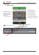
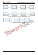
The panel of SGCAN300 is as follows:
Fig. 2 – SGCAN300 Panel Drawing
Table 6 – Terminal Connection Description
No.
Function
Cable
Size
Note
1
DC Power Input B-
1.0mm
2
Connect with negative pole of DC power.
2
DC Power Input B+
1.0mm
2
Connect with positive pole of DC power.
3
Programmable Digital
Input
0.5mm
2
Connecting with B- is effective, it is used for bus switch
status judgement.
4
RS485-TR
0.5mm
2
If terminal resistance matching is required to short
connect with Terminal 5, otherwise it is suspended.
5
RS485-A(+)
0.5mm
2
RS485 communication interface.
6
RS485-B(-)
0.5mm
2
7
MSC1-TR
0.5mm
2
If terminal resistance matching is required to short
connect with Terminal 8, otherwise it is suspended.
8
MSC1-CANH
0.5mm
2
CANBUS communication interface.
9
MSC1-CANL
0.5mm
2
10
MSC2-TR
0.5mm
2
If terminal resistance matching is required to short
connect with Terminal 11, otherwise it is suspended.
11
MSC2-CANH
0.5mm
2
CANBUS communication interface.
12
MSC2-CANL
0.5mm
2
13
FIBER-TX
/
Optical fiber communication interface, SC connector
with lock.
14
FIBER-RX
/
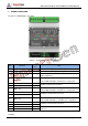
NOTE 1: Please place the dial switch 8 on “OFF” before power on, otherwise the power-on module cannot work
normally.