
User Manual


SGCAN300 CANBUS RELAY MODULE USER MANUAL
SGCAN300 CANBUS Relay Module 2020-08-28 Version 1.0 Page 8 of 12
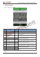
Table 5 –Dial Switch Functions
Dial Sequence
Function
1
Effective Type of Input Port 0: Close is effective 1: Open is effective
2
MSC1 Baud Rate 00:250kbps
01(The third is 1): 50kbps
10(The second is 1): 125kbps
11:500kbps
3
4
MSC 2 Baud Rate 00:250kbps
01(The fifth is 1): 50kbps
10(The fourth is 1): 125kbps
11:500kbps
5
6
RS485 Baud Rate 0:9600bps 1:19200bps
7
Optical Fiber Mode 0: Optical fiber is connected with CAN1.
(Input port should be effective)
1: Optical fiber is connected with RS485.
(Input port should be effective)
8
Test Mode 1: Lamp test function. Each dial switch corresponds to an LED
indicator light, light on when is 1.
NOTE: “ON” of dial switch is 1 and “Non-ON” is 0. There need power on again when baud rate changed.
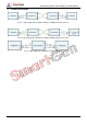
4.2 MUTUAL CONVERSION OF MSC1 AND OPTICAL FIBER
When the digital input is effective, the dial switch 7 is placed to Non-ON, at which time the MS1 is
connected with the optical fiber. The baud rate can be selected by dial switch 2 and 3. The other
SGCAN300 module will go to the same setup. Connecting the optical fiber communication lines of two
SGCAN300 modules, then the MSC1 interface of the two modules can be converted through the optical
fiber.
4.3 MUTUAL CONVERSION OF RS485 AND OPTICAL FIBER
Place the dial switch 7 to ON, then the RS485 is connected with the optical fiber. The baud rate can be
selected by dial switch 6. The other SGCAN300 module will go to the same setup. Connecting the
optical fiber communication lines of two SGCAN300 modules, then the RS485 interface of the two
muddles can be converted through the fiber.
4.4 MUTUAL CONVERSION OF MSC1 AND MSC2
When the digital input is effective, then the MSC1 is connected with the MSC2. The baud rate can be
selected by dial switch 2,3,4,5, then the interfaces of MSC1 and MSC2 are converted