SGCAN300 CANBUS RELAY MODULE USER MANUAL SMARTGEN (ZHENGZHOU) TECHNOLOGY CO., LTD.
Chinese trademark English trademark SmartGen — make your generator smart SmartGen Technology Co., Ltd. No.28 Jinsuo Road, Zhengzhou, Henan Province, China Tel: +86-371-67988888/67981888/67992951 +86-371-67981000(overseas) Fax: +86-371-67992952 Email: sales@smartgen.cn Web: www.smartgen.com.cn www.smartgen.cn All rights reserved.
SGCAN300 CANBUS RELAY MODULE USER MANUAL Table 2 Notation Clarification Sign NOTE CAUTION! WARNING! Instruction Highlights an essential element of a procedure to ensure correctness. Indicates a procedure or practice, which, if not strictly observed, could result in damage or destruction of equipment. Indicates a procedure or practice, which could result in injury to personnel or loss of life if not followed correctly. SGCAN300 CANBUS Relay Module 2020-08-28 Version 1.
SGCAN300 CANBUS RELAY MODULE USER MANUAL CONTENT 1 2 3 4 5 6 7 8 OVERVIEW………………………………………………………………………………….……………….5 PERPORMANCE AND CHARACTERISTICS……………………………………………………………5 SPECIFICATION…………………………………………………………………………………………….6 OPERATION…………………………………………………………………………………………………7 4.1 PANEL INDICATION…………………………………………………………………………………...7 4.2 CONVERSION OF CAN1 AND OPTICAL FIBER…………………………………………………..8 4.3 CONVERSION OF RS485 AND OPTICAL FIBER………………………………………………….8 4.4 CONVERSION OF CAN1 AND CAN2……………………………………………………………….
SGCAN300 CANBUS RELAY MODULE USER MANUAL 1 OVERVIEW SGCAN300 CANBUS RELAY MODULE can realize the mutual conversion between MSC1 and optical fiber, MSC1 and MSC2, RS485 and optical fiber. Using the module can increase the communication distance of MSC or RS485.
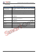
SGCAN300 CANBUS RELAY MODULE USER MANUAL 3 SPECIFICATION Table 3 – Performance Parameter Items Contents Operating Voltage DC 8V~35V, Continuous Power Supply, DC Reverse Connection Protection Power Consumption <2W RS485 Port Isolation, Half Duplex, Baud Rate: 9600bps and 19200bps are optional CAN Port Isolation, Baud Rate: 50kbps, 125kbps, 250kbps and 500kbps are optional Optical Fiber Port Max. Transmission Distance: 10km, Type: SC Vibration 5 - 8 Hz: ±7.
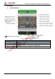
SGCAN300 CANBUS RELAY MODULE USER MANUAL 4 OPERATION 4.1 PANEL INDICATION Fig. 1 – SGCAN300 Panel Indicator NOTE: Partial indicator description. Table 4 – Indicators Description Indicator Note POWER Normally light on DIN Normally light on when effective TX Fast flash (5 times per second) when sending the data RX Fast flash (5 times per second) when receiving the data SGCAN300 CANBUS Relay Module 2020-08-28 Version 1.
SGCAN300 CANBUS RELAY MODULE USER MANUAL Table 5 –Dial Switch Functions Dial Sequence Function 1 Effective Type of Input Port 2 MSC1 Baud Rate 00:250kbps 01(The third is 1) :50kbps 10(The second is 1) :125kbps 11:500kbps MSC 2 Baud Rate 00:250kbps 01(The fifth is 1) :50kbps 10(The fourth is 1) :125kbps 11:500kbps 6 RS485 Baud Rate 0:9600bps 7 Optical Fiber Mode 0: Optical fiber is connected with CAN1. (Input port should be effective) 1: Optical fiber is connected with RS485.
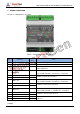
SGCAN300 CANBUS RELAY MODULE USER MANUAL 5 WIRING CONNECTION The panel of SGCAN300 is as follows: Fig. 2 – SGCAN300 Panel Drawing Table 6 – Terminal Connection Description No. Cable Size Function Note 1 DC Power Input B- 1.0mm2 Connect with negative pole of DC power. 2 DC Power Input B+ 1.0mm2 Connect with positive pole of DC power. 3 Programmable Input 0.5mm2 Connecting with B- is effective, it is used for bus switch status judgement. 4 RS485-TR 0.
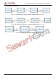
SGCAN300 CANBUS RELAY MODULE USER MANUAL 6 TYPICAL APPLICATION Fig. 3 – Typical Application Diagram of MSC1 and Optical Fiber Conversion Fig. 4 –Typical Application Diagram of RS485 and Optical Fiber Conversion Fig. 5 –Typical Application Diagram of MSC1 and MSC2 SGCAN300 CANBUS Relay Module 2020-08-28 Version 1.
SGCAN300 CANBUS RELAY MODULE USER MANUAL 7 CASE DIMENSIONS AND INSTALLATION Fig.6 - Case Dimensions and Installation (Unit: mm) SGCAN300 CANBUS Relay Module 2020-08-28 Version 1.
SGCAN300 CANBUS RELAY MODULE USER MANUAL 8 TOUBLESHOOTING Table 7 –Troubleshooting Symptoms Possible Solutions Communication failure of MSC1 and MSC1 of the other module 1.Check communication line and communication terminal resistance; 2.Check digital input status and effective type; 3.Check whether the communication baud rate is consistent with the controller; 4.Check whether the dial switch 7 is Non-ON; 5.Observe the communication indicator light to judge the communication error.