
User Manual

CMM366A-4G Cloud Monitoring Communication Module User Manual Page 10 of 16
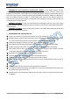
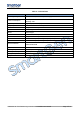
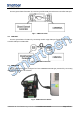
4.10 TERMINAL
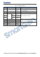
Table 4 – Terminals Description
No.
Function
Cable Size
Note
1
B-
1.0mm
2
Connected with negative of starter battery.
2
B+
1.0mm
2
Connected with positive of starter battery. 3A
fuse is recommended.
3
Digital Input 1
1.0mm
2
Active when connect to B-.
4
Digital Input 2
1.0mm
2
Active when connect to B-.
5
Relay
Output
Normally
Open
1.0mm
2
Volt free output with 1A DC30V.
6
Common
1.0mm
2
7
Normally
Close
1.0mm
2
8
RS485 B(-)
0.5mm
2
Impedance-120Ω shielding wire is recommended,
its single-end earthed.
9
RS485 A(+)
0.5mm
2
10
RS485 (SCR)
0.5mm
2
11
RS232 RX
0.5mm
2
RS232 port.
12
RS232 TX
0.5mm
2
13
RS232 GND
0.5mm
2