
User's Manual


Revised: Version 2
Dated: February 1, 2011
<
Introduction
Congratulations, you have just purchased the
PivotScout™, one of the most advanced irrigation
management tools available.
PivotScout™
PivotScout™ is an add-on device for the SmartCrop®
Base Station, which provides information gathered
directly from the pivot and sends this information
directly to the grower’s home computer. This system
measures the GPS coordinates from the pivot to show
the Grower the movement of the pivot, as well as, the
pressure. In knowing the pressure of the pivot, the
Grower would then know if the pivot system was
active or not. With the SmartCrop® Base Station
reading ambient and canopy temperatures and
tracking rain events, the Grower would know whether
to turn the pivot off or not.
PivotScout™ communicates with the SmartCrop®
Base Station to reliably monitor the pivot’s status
including location and activity.
Guidebook Conventions
To highlight the most important points – we have used
a set of simple icons, which draw attention to key
information and settings.
Key:
The Check Icon indicates a setting that
we recommend you use or enable.
The Info Icon highlights important facts
and information about PivotScout™, to
help you make better use of the
product.
The Hazard Icon highlights areas where
potential problems can arise.
Important Safety Precautions
Only Smartfield trained and certified installers
are authorized to install and maintain
equipment; non-certified installations void
equipment warranty.
Important: DO NOT begin installation until all
utility lines have been located and marked by
your local utility company. Digging without
knowing the location of utility lines can result in
a damaged system, injury or death.
This manual contains important information
about the installation, operation and safe use
of this product. This information should be
given to the owner and / or operator of this
equipment.
Warning: Before installing this product, read
and follow all warning notices and instructions,
which are included. Failure to follow safety
warnings and instructions can result in severe
injury or property damage.
CAUTION: To comply with FCC RF exposure
compliance requirements, a separation
distance of 20 cm must be maintained
between the antenna of this device and all
persons.
C
Contents
One (1) PivotScout™ system
One (1) RF Antenna
One (1) Pressure switch
Two (2) hose clamps
O
Other Materials Needed
¾ inch pipe 90º elbow with ¼ inch Reducing Bushing
H
Hardware Kit
Seven (7) ¾ x 2 ¾ bolts
Two (2) ¾ x ½ bolts
One (1) four arm knob
Eight (8) ¾ locknut
One (1) spade
T
Tools Needed
5/16 inch nut driver
Flathead screwdriver
20-foot extension ladder
Crescent Wrench
Thread Sealant
Revised: Version 2
Dated: February 1, 2011
=
I
Installation
1. Location
a. The PivotScout™ system should be
installed on the first open drop
location of the second or third Pivot
tower. Note: Easiest to locate where
installer can see the tower ladder.
2. Installing Pipe
a. Remove the Pivot cap
b. Install the ¾ inch pipe 90º elbow with
¼ inch reducing bushing into the
opening using thread sealant, install
bushing to elbow
c. Using thread sealant, install elbow to
pivot so as to prevent water leaks.
d. Using thread sealant install pressure
sensor into bushing.
3. Mounting PivotScout™
a. Mount the PivotScout™ system using
the provided hose clamps.
Make sure the attached Solar
Panel is facing up.
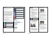
4. Mounting & Connecting RF Antenna
a. Place the RF Antenna on the Solar
Panel mounting bracket tab
b. Locate the RF Antenna cable and
fasten to the correct outlet found on
the bottom of the system.
Figure 1: Showing the RF Antenna outlet
located on the bottom of the system.
5
5.
Connecting the pressure transducer
a. Inside the PivotScout™ system, locate
the green J3 terminal strip, found in the
bottom right corner. Connect the wires
to the appropriate terminal using the
printed reference designators.
Red – “U+”
White – “Pressure”
Black & Shield – “Ground”
Figure 2: Showing the J3 terminal strip for
the pressure transducer wires.
6
6.
Connecting the Solar Panel
a. Locate the Solar Panel power cord.
With the system door still open, run the
cord through the opening at the bottom
of the system and plug into the
motherboard pins labeled “Solar
Panel”.
7.
Connecting the Battery
a. Locate the battery power cord and plug
into the motherboard pins labeled
“Battery”.
i. Verify that the power LED display
lights up and the motion LED flashes.
Figure 3: Showing the Battery & Solar Panel
power cords plugged into the motherboard
labeled “Battery” and “Solar Panel” pins.
8
8.
Verifying communication
a. Back at the Base Station, verify the
PivotScout™ serial numbers appear
on the Base Station screen.
b. Scroll and select each serial number.
Then scroll and press “Finish” twice to
go back to home screen.