Temperature Monitor System 2 (TMS-2) Connections and Operations 25 March 2005 R S S SmarTek Systems 410-315-9727 sales@smarteksys.com www.smarteksys.
Limited Warranty © Copyright 1997-1998 SmarTek Systems, Inc. All Rights reserved. SmarTek Systems, Inc 14710 Kogan Drive Woodbridge, VA 22193 Phone: 703-680-6554 or 410-315-9727 LIMITED SOFTWARE WARRANTY. SmarTek Systems warrants that the original disks are free from defects in material and workmanship, assuming normal use for a period of 90 days from the date of purchase. If a defect occurs during this period, you may return your faulty disk to SmarTek Systems, along with a copy of your dated invoice.
Limitations on Use LIMITATIONS ON USE. Software provided on any medium (disks and Electrically Erasable Read-Only Memories (EEROMs)), or provided with or as components of the System Printed Circuit Board (PCB) shall not be copied, reverse engineered, reverse compiled, or otherwise manipulated to provide access to the code. SmarTek Systems grants a personal, and non-exclusive right to use, in object code form, all software and related documentation furnished with this system.
TMS-2 Overview The Temperature Monitor System 2 (TMS-2) is used to collect, process, and log temperature data from a small or large number of distributed digital temperature sensors. The heart of theTMS-1 system is the SmarTek Systems Universal Sensor Interface (USI) processor which is designed to operate around the clock in adverse environments.
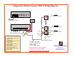
Temperature Monitor System (TMS-2) Wiring Diagram Sys Universal Sensor Interface-Front 1 3 5 7 9 Aux RS-232 2 4 6 8 Reset 10 Temperature Sensor (s) AC/DC 12 VDC USI SYS to PC Cable Universal Sensor Interface-Rear -+ 1 Temperature Sensor (s) 14 Orange Orange Opto-Isolated Relays (6) Orange USI Rear Panel Green Connector 1 2 3 4 5 6 7 8 9 10 11 12 13 14 Common Emitter for Relays 5 and 6 Relay 6 Collector Relay 5 Collector Common Emitter for Relays 3 and 4 Relay 4 Collector Relay 3 Collecto
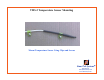
TMS-2 Temperature Sensor Mounting Mount Temperature Sensor Using Clips and Screws R S S SmarTek Systems 410-315-9727 sales@smarteksys.com www.smarteksys.
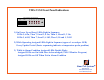
TMS-2 USI Front Panel Indications Sys Universal Sensor Interface-Front 1 3 5 7 9 Aux RS-232 2 4 6 8 Reset 10 1) On Power Up or Reset, LEDs Light in Sequence: LEDs 5, 6 On, Then 7, 8 and 3, 4 On, Then 9, 10 and 1, 2 On LEDs 5, 6 Off, Then 7, 8 and 3, 4 Off, Then 9, 10 and 1, 2 Off 2) While Operating Assigned LEDs Light in Sequence (approx 1 second per LED) Every Update Period (Faster sequencing indicates a temperature probe problem) 3) While in Alarm Condition Assigned LEDs Double Flash: Assigned L
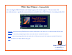
TMS-2 Start Window - Connectivity After starting the TMS-2 Monitor and Setup Program, this window appears. The user must click one of the buttons to specify the connectivity between the PC where TMS-2 Monitor is running and the USI. Network – Connectivity using TCP/IP sockets between the PC and a serial device server connected to the USI Sys Port. Modem – Connectivity using dial up modems connected to the PC and the USI Sys Port.
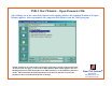
TMS-2 Start Window – Open Parameter File After clicking one of the connectivity buttons on the opening window, this Standard Windows File Open Window appears. Select a parameter file (.smp) and click Open to start the TMS-2 program. R The file selection is not critical when connected to a USI that is already setup and operating. As shown on the next page, as soon as the TMS-2 Monitor Main window appears, the user should perform a Get TMS ID and then a Get TMS Parameters via the TMS-USI pull-down menus.
TMS-2 Main Display - Startup On Startup: 1) Click TMS-USI Menu/Get TMS ID 2) Click TMS-USI Menu/Get TMS Parameters To Remove Yellow Mismatch Flag 3) Click TMS-USI Menu/Get TMS Date and Time 4) Click in Mode Field to Change Mode to 1 1 2 4 3 Communication Mode/Status Facility Description Text R S S SmarTek Systems 410-315-9727 sales@smarteksys.com www.smarteksys.
TMS-2 Main Display - Startup 2 1) Use Settings Menu/Comm Port to Modify Comm Port Settings: Comm Port Number = PC Comm Port Used Baud Rate = 115200 bps Data Bits = 8 Parity = None Stop Bits = 1 HW Flow Control - Unchecked SW Flow Control - Unchecked Set DTR Line High - Checked Set RTS Line High - Checked 1 2) Clicking the Save Image Button or the Save Image Menu Item on any Display will Save the Window As a .
TMS-2 Main Display Complete Descriptive Text for Selected Probe Click to Acknowledge All Alarms at Once Temperature Probe Descriptive Text - Right Click in Field to open Probe Parameter Editor Window (Pg 13) Color Coded Temperature Measurement Readout - Left Click in Field to Select - Right Click in Field to Acknowledge Alert - Double Click in Field to Open History Display as shown on page 15 R S S SmarTek Systems 410-315-9727 sales@smarteksys.com www.smarteksys.
TMS-2 Main Display Readout of General Parameter Settings Click This Button to Start or Stop A Communication Process Yellow Flag Indicates Possible Parameter Differences Between TMS-2 Monitor and the USI. Use TMS-USI Menu /Send Parameters or Get Parameters To Remove Yellow Mismatch Flag. R S S SmarTek Systems 410-315-9727 sales@smarteksys.com www.smarteksys.
Edit Temperature Probe Parameters To Open The Probe Parameter Edit Window, Right Click on Probe Description Field. Click in Upper/Lower Field to Increment/Decrement Enter/Modify Descriptive Text for the Probe Click in Upper/Lower Field to Increment/Decrement R S S NOTE: Probe Serial Numbers must match the electronic serial numbers in the digital temperature probes. Probe Serial Numbers should not be modified unless replacing a failed probe or adding probes.
Edit General Parameters To Open The General Parameters Edit Window, Click the Settings Menu/Edit TMS General Parameters Menu Item on the Main TMS-2 Window. Enter/Modify File Name for Archive Data File Storage Upon Down Load from the USI Click in Field to Modify (Default-Powered) (Default-Deg_F) Enter/Modify Descriptive Text for the Facility Click in Upper/Lower Field to Increment/Decrement Click in Field to Modify (Default-Periodic) R S S SmarTek Systems 410-315-9727 sales@smarteksys.com www.
TMS-2 Temperature Measurement History Display To Open The Temperature Measurement History Window, Double Click on the Measurement Readout Field Present Time is at the Right Edge of Display Max Alarm Threshold Temperature Measurement Min Alarm Threshold Click in Upper/Lower Field to Select Probe Mouse Cursor Readout R S S SmarTek Systems 410-315-9727 sales@smarteksys.com www.smarteksys.
TMS-2 TMS-USI Menu Get TMS ID – USI responds with its ID (TMSxxxx) Get TMS Parameters – USI responds with its parameters Get TMS Date and Time – USI responds with its date and time Get TMS Archive Data – USI sends the archive data line by line until complete Archive file is saved in the Arch_Data sub-folder using the name specified in the General Parameters. The archive file is a space delimited, spread sheet ready file.
TMS-Archive Retrieval TMS-USI Menu/Get TMS Archive Data – USI sends the archive data line by line until complete. Archive file is saved in the Arch_Data sub-folder using the name specified in the General Parameters. The archive file is a space delimited, spread sheet ready file.