
Configuration And Connection Owner's manual

SmarTek Systems (www.smarteksys.com)
8
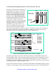
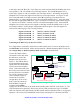
Note: Each SAS-RI used as slaves (SAS0002 thru SAS0006) in Figure 7 must be factory
modified for receive only capability. They are not interchangable with the SAS-RI used as the
Master (corresponding to SAS0001).
Figure 7 Connecting Multiple SAS-RI Shelf Mount Units to a Single SAS-CT
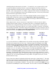
Data/Power Cable(s) From
SAS-1(s)
SAS-CT To SAS-RI (RJA)
Cable (For Operation)
112
SAS Cabinet Termination
DC IN
Fuse
SAS-RI (Shelf Mount)
For
SAS0001
For
SAS0002
RJARJB
For
SAS0003
RJARJB
RJARJB
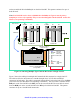
Power 8 to 24 VDC
1 NC
2 Blue TxD+ (In)
3 Blk of Blu TxD- (In)
4 Green RxD+ (Out)
5 Blk of Grn RxD- (Out)
6 NC
7 NC
8 NC
9 NC
10 Blk of Red GND
11 Red VDC (Out)
12 Shield GND
+
-
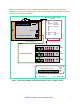
Relays and Power Connector
Activity
LED
CE - Common Emitter
Pwr - 8 to 24 VDC
1A
1B
2A
2B
3A 4A 5A
4B3B 5B
CE
CE
Gnd
Pwr