
Installation Guide
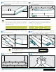
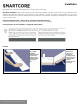
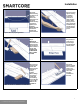
Table Of Contents

Installation
Electric Radiant Floors
: consist of electric cables (or) mats of electrically conductive materials mounted on the subfloor below
the floor covering. Mesh systems are typically embedded in thin-set. When embedding the system components, use
cementitious patching and leveling compounds that meet or exceed Shaw’s maximum moisture level and pH requirements.
Use of gypsum-based patching and/or leveling c
ompounds which contain Portland or high alumina cement and meet or exceed
the compressive strength of 3,000 psi are acceptable.
Hydronic Radiant Floors
: pump heated water from a boiler through tubing laid in a pattern under the flooring. Typically installed
in channels under a wooden subfloor (or) imbedded in concrete slabs. Requires the installer follow a specific nailing pattern to
avoid penetration of the heat system.
C. EXISTING FLOOR COVERINGS
Flooring can be installed over most existing hard–surface floor coverings, provided that the existing floor surface is fully adhered, clean,
flat, dry, structurally sound and free of deflection.
Existing sheet vinyl floors should not be heavily cushioned and not exceed more than one layer in thickness. Soft underlayment
and soft substrates will compromise the product's locking ability as well as diminish its indentation resistance.
Installation is NOT allowed over any type of carpet.
Do NOT install over wood floors adhered to concrete.
Never use solvents or citrus adhesive removers to remove old adhesive residue. Solvent residue left in and on the subfloor may
affect the new floor covering.
This product can be installed over existing ceramic/porcelain tile products with up to a 1/4 inch wide grout joint.If the grout joint
width exceeds 1/4 inch, a cementitious patching compound should be used to fill the grout joint to make it smooth with the
surface of the tile.
RAISED ACCESS PANEL SUBFLOORS
Raised access panels must be stable, level, flat, free and clean of existing adhesives
24" x 24" panels are recommended.
Lippage (variation of height) between of panels must notexceed 0.295” (0.75 mm)
Gaps between panels must not exceed 0.039” (1 mm)
There should be no deflection of the individual panels – Concave less than 0.0295” (0.75 mm)
Flatness 1/8” in 10’
Stagger the flooring tiles/planks to overlap the access panels
Telegraphing of access panel seams may be visible and is not considered a product defect nor warranted by the flooring
manufacturer.
If needed, overlay the panels with a 1⁄4” (6 mm) plywood and properly fasten to the access panels prior to the installation of the
floorcovering. Prior to underlayment installation, repair any loose or unstable panels. Use the appropriate installation methods for the
pr
oduct.
III. INSTALLATION
Tools: Tape Measure, Utility Knife, Jigsaw, Tapping Block or Rubber Mallet, Pull Bar, ¼" Spacers, T-Square, Safety Glasses,
Broom or Vacuum and, if necessary, tools for subfloor repair.
Floating Installation
WPC flooring is designed to be installed utilizing the floating method. Proper expansion space 1/4” (6.35 mm) is required. Undercut
3
For reference purposes only if printed or downloaded.