
Installation Instruction
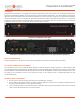
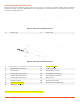
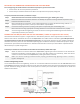
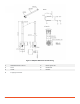
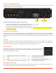
Table Of Contents
- PowerLine Coordinator™
- Overview
- PowerLine Coordinator Front View
- PowerLine Coordinator Rear View (Dual Power Option shown for representative purposes)
- Safety Information
- Follow the guidelines in this section to ensure proper operation and safe use of the PowerLine Coordinator.
- FCC Safety Compliance Statement
- General Safety Guidelines
- Before Beginning the Installation
- Figure 1: PowerLine Coordinator Layout
- Figure 2: PowerLine Coordinator Layout
- *All DC input to the system must be protected by an adequately sized DC circuit breaker.
- Deploying the PowerLine Coordinators on YOUR Network
- Prior to beginning the actual PowerLine Coordinator deployment, perform these tasks:
- To deploy PowerLine Coordinators, follow these steps:
- Connecting the 866/915 Mhz and 2.4 GHz Antennas
- To attach your antenna or antenna cable to the PowerLine Coordinator, follow these steps:
- Antenna and Lightening Arrestor
- Figure 3: Lightning Surge Arrestor
- Figure 4: 866/915 MHz Antenna Mounting
- Connecting the Power Cables
- The PowerLine Coordinator receives power through the external power sources. Figure 2-4 shows the power options for the PowerLine Coordinator with AC/DC configuration.
- Figure 7: PowerLine Coordinator Power Options
- The PowerLine Coordinator power options are listed below:
- Connecting the LAN Cables
- The PowerLine Coordinator connects to the network through a 10/100/1000 Ethernet interface using SFP based RJ45 Ethernet or fiber connection. Use only double shielded Ethernet cables grounded at both ends for protection of the communication infrastruc...
- USB PORT
- The PowerLine Coordinator is provisioned with a USB console/maintenance port. This port is used by your Smart Wires’ representative to access the system for configuration/diagnostic purposes only and is not populated with any cables during normal use....
- AUX Connector
- The PowerLine Coordinator is provisioned with an AUX connector for Opto-isolated type external inputs and DC power sources. Contact your Smart Wires’ representative for additional information for provisioning these input/power contacts.
- ConFIGURing the SYSTEM
- The PowerLine Coordinator comes preconfigured for your particular installation. There are no user configurable options on the unit. Contact your Smart Wires’ representative for making any changes as needed.
- About Smart Wires

© 2018 Smart Wires | www.smartwires.com PowerLine Coordinator - Installation Instruction Sheet 5
CONNECTING THE POWER CABLES
The PowerLine Coordinator receives power through the external power sources. Figure 2-4 shows the power options for the
PowerLine Coordinator with AC/DC configuration.
Figure 7: PowerLine Coordinator Power Options
The P
owerLine Coordinator power options are listed below:
• Each PowerLine Coordinator receives redundant power supplies.
• AC/AC or DC/DC configurations with wide-range power suppliers are also available.
• Provide the redundant power inputs as per ordered configuration.
• Power rating of each PowerLine Coordinator unit is 20 W maximum (~420 mA @ 48 VDC nominal input / ~100 mA @
220 VAC nominal input).
CONNECTING THE LAN CABLES
The PowerLine Coordinator connects to the network through a 10/100/1000 Ethernet interface using SFP based RJ45 Ethernet
or fiber connection. Use only double shielded Ethernet cables grounded at both ends for protection of the communication
infrastructure and components. Contact your Smart Wires’ representative for buying additional Ethernet/Fiber cables as
needed.
USB PORT
The PowerLine Coordinator is provisioned with a USB console/maintenance port. This port is used by your Smart Wires’
representative to access the system for configuration/diagnostic purposes only and is not populated with any cables during
normal use. Contact your Smart Wires’ representative for additional information as needed.
AUX CONNECTOR
The PowerLine Coordinator is provisioned with an AUX connector for Opto-isolated type external
inputs and DC power sources. Contact your Smart Wires’ representative for additional information for
provisioning these input/power contacts.
1 5V DC Output with maximum 1 A Load capacity 5 Power Source (P1) for Input N1 Terminal
2 GND 6 Opto-isolated Input N1 Terminal
3 GND 7 Power Source (P2) for Input N2 Terminal
4 3V3 DC Output with maximum 1 A Load capacity 8 Opto-isolated Input N2 Terminal
CONFIGURING THE SYSTEM
The PowerLine Coordinator comes preconfigured for your particular installation. There are no user configurable options on the
unit. Contact your Smart Wires’ representative for making any changes as needed.
(48 VDC)
(100-240 VAC)