
Installation Instruction
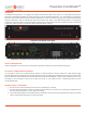
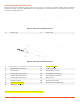
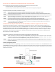
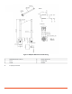
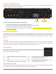
Table Of Contents
- PowerLine Coordinator™
- Overview
- PowerLine Coordinator Front View
- PowerLine Coordinator Rear View (Dual Power Option shown for representative purposes)
- Safety Information
- Follow the guidelines in this section to ensure proper operation and safe use of the PowerLine Coordinator.
- FCC Safety Compliance Statement
- General Safety Guidelines
- Before Beginning the Installation
- Figure 1: PowerLine Coordinator Layout
- Figure 2: PowerLine Coordinator Layout
- *All DC input to the system must be protected by an adequately sized DC circuit breaker.
- Deploying the PowerLine Coordinators on YOUR Network
- Prior to beginning the actual PowerLine Coordinator deployment, perform these tasks:
- To deploy PowerLine Coordinators, follow these steps:
- Connecting the 866/915 Mhz and 2.4 GHz Antennas
- To attach your antenna or antenna cable to the PowerLine Coordinator, follow these steps:
- Antenna and Lightening Arrestor
- Figure 3: Lightning Surge Arrestor
- Figure 4: 866/915 MHz Antenna Mounting
- Connecting the Power Cables
- The PowerLine Coordinator receives power through the external power sources. Figure 2-4 shows the power options for the PowerLine Coordinator with AC/DC configuration.
- Figure 7: PowerLine Coordinator Power Options
- The PowerLine Coordinator power options are listed below:
- Connecting the LAN Cables
- The PowerLine Coordinator connects to the network through a 10/100/1000 Ethernet interface using SFP based RJ45 Ethernet or fiber connection. Use only double shielded Ethernet cables grounded at both ends for protection of the communication infrastruc...
- USB PORT
- The PowerLine Coordinator is provisioned with a USB console/maintenance port. This port is used by your Smart Wires’ representative to access the system for configuration/diagnostic purposes only and is not populated with any cables during normal use....
- AUX Connector
- The PowerLine Coordinator is provisioned with an AUX connector for Opto-isolated type external inputs and DC power sources. Contact your Smart Wires’ representative for additional information for provisioning these input/power contacts.
- ConFIGURing the SYSTEM
- The PowerLine Coordinator comes preconfigured for your particular installation. There are no user configurable options on the unit. Contact your Smart Wires’ representative for making any changes as needed.
- About Smart Wires

© 2018 Smart Wires | www.smartwires.com PowerLine Coordinator - Installation Instruction Sheet 3
DEPLOYING THE POWERLINE COORDINATORS ON YOUR NETWORK
Prior to beginning the actual PowerLine Coordinator deployment, perform these tasks:
• Ensure that an RF site survey has been performed.
• Ensure that your network infrastructure devices are operational and properly configured.
T
o deploy PowerLine Coordinators, follow these steps:
Step 1 Obtain the PowerLine Coordinator location map created during your building site survey.
Step 2
Review the PowerLine Coordinator locations and identify the specific mounting methods required for each
PowerLine Coordinator location.
Step 3
Mount the PowerLine Coordinator at the indicated destination using the specified mounting method. For
specific mounting instructions, contact your Smart Wires’ representative.
Step 4 Connect the chassis ground to a proper ground point as required by your local building code.
Step 5
Mount all antennas using appropriate mounting hardware. Ensure that base of the antenna is properly
secured and grounded. Use lightning arrestors for exterior mounting with additional ground connections as
required by the arrestor part selected.
CONNECTING THE 866/915 MHz AND 2.4 GHz ANTENNAS (*2.4Ghz not supported in this version)
The PowerLine Coordinator supports a single antenna or dual diversity antennas. Two N-Type antenna connectors are
there for each radio on the back of the unit for the 866/915MHz and 2.4 GHz radio for redundancy (* 2.4 GHz operation is
not supported in this version and is provisioned for future use). The appropriate frequency for your specific installation is
selected at the factory and is not user selectable. Depending upon the features ordered, a cellular backup option may be
provisioned in your PowerLine Coordinator for redundant communication. Contact your Smart Wires’ representative for
details about your system configuration.
To attach your antenna or antenna cable to the PowerLine Coordinator, follow these steps:
Step 1
Attach an antenna or antenna cable to the 866/915MHz, Right N-Type antenna connector on the back of the
PowerLine Coordinator and hand tighten. If you are using two antennas for redundancy, attach the second
antenna or antenna cable to the 866/915MHz, Left N-Type antenna connector.
Step 2
Make sure antenna-mounting bracket should be properly grounded through lightning arrestor as shown in
Figure 3 and Figure 4.
Antenna and Lightening Arrestor
The recommended antenna and lightening arrestor for use with the PowerLine Coordinator are the OMB.8912.05F21 and
ALQP-NMNFB respectively. Equivalent antennas may be used, but the EIRP of the setup shall not exceed the limits imposed
by local authorities having jurisdiction over the RF spectrum. Contact your Smart Wires’ representative for details and
additional information.
Figure 3: Lightning Surge Arrestor