
Installation Instruction
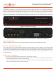
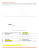
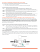
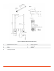
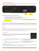
Table Of Contents
- PowerLine Coordinator™
- Overview
- PowerLine Coordinator Front View
- PowerLine Coordinator Rear View (Dual Power Option shown for representative purposes)
- Safety Information
- Follow the guidelines in this section to ensure proper operation and safe use of the PowerLine Coordinator.
- FCC Safety Compliance Statement
- General Safety Guidelines
- Before Beginning the Installation
- Figure 1: PowerLine Coordinator Layout
- Figure 2: PowerLine Coordinator Layout
- *All DC input to the system must be protected by an adequately sized DC circuit breaker.
- Deploying the PowerLine Coordinators on YOUR Network
- Prior to beginning the actual PowerLine Coordinator deployment, perform these tasks:
- To deploy PowerLine Coordinators, follow these steps:
- Connecting the 866/915 Mhz and 2.4 GHz Antennas
- To attach your antenna or antenna cable to the PowerLine Coordinator, follow these steps:
- Antenna and Lightening Arrestor
- Figure 3: Lightning Surge Arrestor
- Figure 4: 866/915 MHz Antenna Mounting
- Connecting the Power Cables
- The PowerLine Coordinator receives power through the external power sources. Figure 2-4 shows the power options for the PowerLine Coordinator with AC/DC configuration.
- Figure 7: PowerLine Coordinator Power Options
- The PowerLine Coordinator power options are listed below:
- Connecting the LAN Cables
- The PowerLine Coordinator connects to the network through a 10/100/1000 Ethernet interface using SFP based RJ45 Ethernet or fiber connection. Use only double shielded Ethernet cables grounded at both ends for protection of the communication infrastruc...
- USB PORT
- The PowerLine Coordinator is provisioned with a USB console/maintenance port. This port is used by your Smart Wires’ representative to access the system for configuration/diagnostic purposes only and is not populated with any cables during normal use....
- AUX Connector
- The PowerLine Coordinator is provisioned with an AUX connector for Opto-isolated type external inputs and DC power sources. Contact your Smart Wires’ representative for additional information for provisioning these input/power contacts.
- ConFIGURing the SYSTEM
- The PowerLine Coordinator comes preconfigured for your particular installation. There are no user configurable options on the unit. Contact your Smart Wires’ representative for making any changes as needed.
- About Smart Wires

© 2018 Smart Wires | www.smartwires.com PowerLine Coordinator - Installation Instruction Sheet 2
BEFORE BEGINNING THE INSTALLATION
Before you begin the installation process, please refer to Figure 1, and Figure 2 to become familiar with the PowerLine
Coordinator’s layout, connectors, 866/915 MHz, and 2.4 GHz location. (* 2.4 GHz operation is not supported in this version
and is provisioned for future use)
Figure 1: PowerLine Coordinator Layout
1
Power 1 LED
2
Power 2 LED
Figure 2: PowerLine Coordinator Layout
1
2.4 GHz LED Indication (* 2.4 GHz operation is not supported in t
his version)
10
100-240 VAC (+10%)
2
866/915 MHz LED Indication
11
2.4 GHz Connector
3
AUX Connector
12
866/915 MHz Connector
4
Dual SFP Ethernet Connectors
13
Optical UART1 RX Connector
5
Optical UART2 RX Connector
14
Optical UART1 TX Connector
6
Optical UART2 TX Connector
15
USB Connector
7
GPS LED Indication
16
GPS Antenna Connector
8
48 VDC nominal (+10%)*
17
Chassis Ground - Two-Hole Lug
9
GSM Antenna Interface
*All DC input to the system must be protected by an adequately sized DC circuit breaker.