X-Port™ 20 Switch (XP20-2000i-B) Installation Guide for any 2000i Equipped with an NEC VT465 or VT560 Projector 99-00539-00 Rev B0
FCC Warning This equipment has been tested and found to comply with the limits for a Class A digital device, pursuant to Part 15 of the FCC Rules. These limits are designed to provide reasonable protection against harmful interference when the equipment is operated in a commercial environment. This equipment generates, uses and can radiate radio frequency energy and, if not installed and used in accordance with the manufacturer’s instructions, may cause harmful interference to radio communications.
Contents Installing an X-Port 20 Serial/Video Switch in a 2000i-DVS ............................................................ 1 To mount the X-Port 20 switch ........................................................................................................................................1 To connect the X-Port 20 switch ......................................................................................................................................5 To connect a guest laptop ...................
ii 99-00539-00 Rev A0
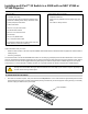
Installing an X-Port™ 20 Switch in a 2000i with an NEC VT465 or VT560 Projector This kit contains: Tools required (but not included): • an antistatic wrist strap • Phillips® screwdrivers • an X-Port 20 switch which includes two stacked circuit boards with installed gender changer and ribbon cable • a 5/32" hex key (available in the accessory kit for the 2000i) • a serial (computer) switch label • wire cutters or sturdy scissors • a video switch label • two 6-32 x 1/4" pan head screws • four #6 star
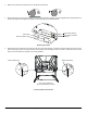
2. Make sure the casters are locked and all four anti-tip feet are extended. 3. Remove the stickers covering the lower DB9 opening and the upper HD15 opening. Place the supplied serial (computer) label over the lower opening and the supplied video label over the upper opening, as illustrated below. Upper HD15 Opening Video Label Lower DB9 (Computer) Opening Serial (Computer) Label Replacing the Labels 4.
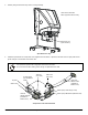
5. Carefully swing the electronics tray down so it hangs vertically. Rear View of 2000i with Back Legs Removed for Clarity Electronics Tray (Open Position) Open Electronics Tray 6. Familiarize yourself with the components of the supplied X-Port 20 switch. In particular, take note of the I²C input jacks and the gender changer on the left side of the bottom card. IMPORTANT It is important to preserve the configuration of the X-Port 20 switch.
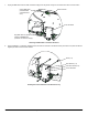
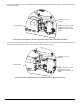
7. Unplug the DB9 cable from the serial controller and plug it into the gender changer on the bottom card of the X-Port 20 switch. Unplug DB9 cable (From Resident Computer Serial Port) Serial Controller X-Port 20 Switch Plug DB9 cable into gender changer on bottom card (connector not shown in image) Rerouting the DB9 Cable to the X-Port 20 Switch 8. Using a Phillips No.
To connect the X-Port 20 switch 1. Attach the loose end of the DB9 female-to-female ribbon cable to the serial controller using the two supplied machine screws. Secure the ribbon cable and serial cable in place, as shown below, using two of the supplied tie wraps. Machine Screws (x 2) Serial Controller Loose End of Ribbon Cable Tie Wraps (x 2) Serial Cable Rerouting the Ribbon Cable 2.
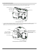
3. Connect the supplied 6" (15.2 cm) I²C cable between the audio amplifier (either I²C jack) and the empty I²C jack on the bottom card of the X-Port 20 switch. Supplied 6" (15.2 cm) I²C Cable Audio Amplifier NOTE: Connect the I²C cable to the empty I²C jack on the bottom card of the X-Port 20 switch. Connecting the Audio Amplifier to the X-Port Serial/Video Switch (Room Control Module Installed) 4. If you don’t have a Room Control Module installed, attach the supplied 6" (15.
5. Locate the tie-wrapped bundle of cables running along the underside of the cabinet. In this bundle is a video cable (labeled RBG 1 IN) that connects directly to the RGB IN port on the projector. Disconnect this cable from the back of the projector, carefully cut the tie wraps that hold the bundle together with a pair of wire cutters or sturdy scissors, and connect the cable to the Video IN port on the top card of the X-Port 20 switch.
8. Swing the electronics tray back to its original position, and insert the two button head screws that you removed earlier. IMPORTANT Before you close the electronics tray, ensure all cables are routed neatly. Use the supplied tie wraps to bundle the cables. To connect a guest laptop Attach the supplied guest laptop cable bundle to the rear of the 2000i as follows: • Connect the HD15 video cable to the Computer 2 Video port on the electronics tray.
2. Turn on the guest laptop. 3. If it’s still unplugged, plug in the 2000i and press the Lamp On button on the Control Panel. 4. Press the Guest Laptop button on the Control Panel to switch to the guest laptop video source. If the initialization screen does not appear on the interactive whiteboard Try activating the external video port on your guest laptop. Some laptops can't display their internal screens and activate the external video port or external monitor at the same time.
Customer Support Contacting SMART Technical Support SMART’s Technical Support team welcomes your call. However, you may first want to contact your local reseller if you experience any difficulties with your SMART product, as they may be able to solve the problem without delay. All SMART products include free telephone, fax and e-mail support. Telephone: 1.866.518.6791 (toll-free in Canada/U.S.) or +1.403.228.5940 (all other countries) (Available 7 a.m. – 6 p.m. Mountain time from Monday to Friday) Fax: +1.