
User manual
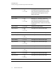
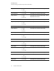
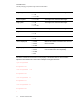
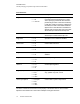
Table Of Contents
- Contents
- Important information
- Chapter 1: About your interactive whiteboard system
- Chapter 2: Installing your interactive whiteboard system
- Chapter 3: Using your interactive whiteboard system
- Appendix 4: Integrating other devices
- Chapter 5: Maintaining your interactive whiteboard system
- Chapter 6: Troubleshooting your interactive whiteboard system
- Before you start
- Determining your interactive whiteboard system’s status
- Resolving interactive whiteboard issues
- Resolving projector issues
- Resolving ECP issues
- Accessing the service menu
- Transporting your interactive whiteboard system
- Appendix A: Remotely managing your system through a network interface
- Appendix B: Remotely managing your system through an RS-232 serial interface
- Connecting your room control system to the ECP
- Projector programming commands
- Appendix C: Remote control code definitions
- Appendix D: Hardware environmental compliance
- Index

A P P E N D I X B
Remotely managing your system through an RS-232 serial interface
72 smarttech.com/kb/170401
Field Possible values Description
target usb2source l = VGA1
l = HDMI1
l = Disabled
Value to set the usb2 switch enabled source to.
Note that this can not be the same as the
usb1source. If it is, USB1 will be used and
USB2 is ignored.
Example:
> set input=vga1
input = vga1
> set input=next
input = composite
> get videoinputs
videoinputs = vga1, composite, hdmi1
> get usb1source
usb1source = vga1
> get usb2source
usb2source = hdmi1
> set usb2source = hdmi1
usb2source = hdmi1
>
Video Control
Video output related controls. The range of values used for these commands should match the range
displayed visually on the OSD. The firmware must handle videofreeze and videomute states
correctly. A change should be made to ensure that videofreeze and videomute are mutually
exclusive.