
User manual
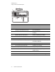

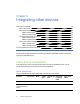
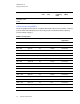
Table Of Contents
- Contents
- Important information
- Chapter 1: About your interactive whiteboard system
- Chapter 2: Installing your interactive whiteboard system
- Chapter 3: Using your interactive whiteboard system
- Appendix 4: Integrating other devices
- Chapter 5: Maintaining your interactive whiteboard system
- Chapter 6: Troubleshooting your interactive whiteboard system
- Before you start
- Determining your interactive whiteboard system’s status
- Resolving interactive whiteboard issues
- Resolving projector issues
- Resolving ECP issues
- Accessing the service menu
- Transporting your interactive whiteboard system
- Appendix A: Remotely managing your system through a network interface
- Appendix B: Remotely managing your system through an RS-232 serial interface
- Connecting your room control system to the ECP
- Projector programming commands
- Appendix C: Remote control code definitions
- Appendix D: Hardware environmental compliance
- Index
C H A P T E R 3
Using your interactive whiteboard system
24 smarttech.com/kb/170401
N O T E S
l For more details on the status of your interactive whiteboard system, go to Determining your
interactive whiteboard system’s status on page 46.
l Low Power mode reduces your interactive whiteboard system’s power consumption when it is
in Standby mode.To set the projector system to enter Low Power mode automatically
whenever it enters Standby mode, hold down the Power and Input buttons at the same
time for five seconds. After five seconds, the Power button blinks amber for two seconds to
indicate that Low Power mode is enabled.
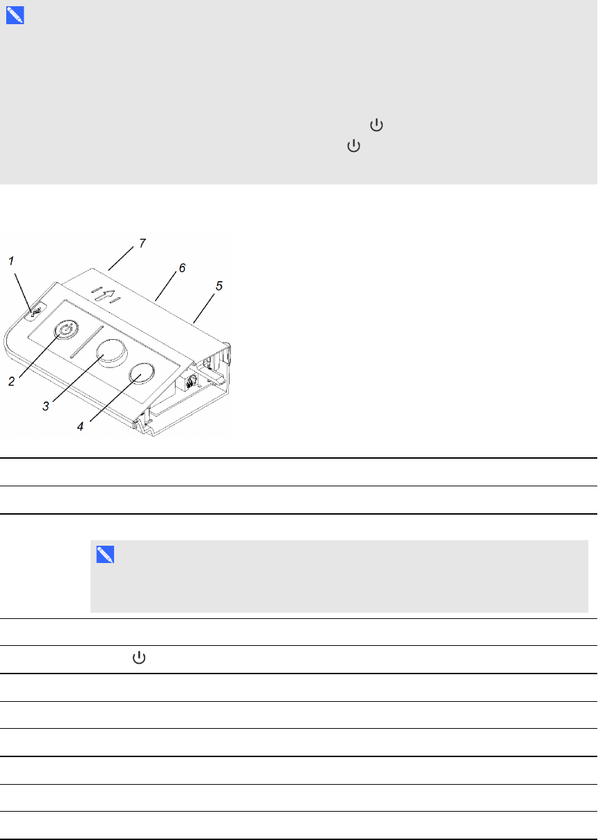
The following diagram and table describe the components of the ECP.
Number Function
Left side
1 USB A receptacle (for USB drives)
N O T E
USB drives that you connect to this receptacle are only accessible to the room
computer (the computer connected to the USB1 receptacle).
Front
2
Power button and status indicator light
3 Volume control
4 Input selection
Back
5 Two mini USB B receptacles (connect to room computer and laptop)
6 11-pin connector (connects to ECP cable harness)
7 4-pin connector (for optional room control)