Room Control Module Installation Guide for the Interactive Whiteboard 99-00360-02 Rev A0
FCC Warning This equipment has been tested and found to comply with the limits for a Class A digital device, pursuant to part 15 of the FCC Rules. These limits are designed to provide reasonable protection against harmful interference when the equipment is operated in a commercial environment. This equipment generates, uses and can radiate radio frequency energy and, if not installed and used in accordance with the instruction manual, may cause harmful interference to radio communications.
Contents Installing the Room Control Module................................................ 1 About the Custom Straight-Through MOD4 I2C Cables.................................1 Removing the Blank Panel.............................................................................2 Completing the Computer 2 (X-Port 20) Serial Panel Connections...............3 Inserting the Room Control Module ...............................................................5 Updating the Control Panel Firmware ................
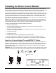
Installing the Room Control Module These instructions explain how to install the SMART Room Control Module (part No. 3000i-RCM). For information about programming the module to work with a third-party system, refer to the Room Control Module Integration Guide for the Rear Projection SMART Board™ 3000i Interactive Whiteboard. You can use a third-party room-control system to change the projector settings for a Rear Projection SMART Board 3000i interactive whiteboard.
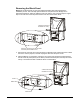
Removing the Blank Panel NOTE: We recommend that you wear the supplied anti-static wrist strap throughout the installation process. This wrist strap protects electronic components from damage due to electrostatic discharge. Attach the adhesive side of the strap to your wrist and wrap the copper tape on the other end of the strip around either of the two screws shown below.
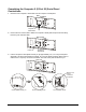
Completing the Computer 2 (X-Port 20) Serial Panel Connections 1 Disconnect the computer 2 serial cable from the computer 2 serial panel. Rear of Cab inet Computer 2 Serial Cable 2 Remove the four screws used to attach the computer 2 serial panel. Keep the screws handy, because you’ll need them later. Rear of Cab inet Screw x 4 3 Computer 2 Serial Panel Pull the computer 2 serial panel towards you by approximately 1/2" (12.7 mm), tilt the panel diagonally, and fit the panel inside the cabinet.
4 Disconnect the MOD4 I2C cable at the top of the computer 2 serial panel. 2 MOD4 I C Cable Rear of Cab in 5 et Run this cable behind the patch panel and through the opening where the blank panel was removed. Rear of Cab inet 2 MOD4 I C Cable 6 Hold the computer 2 serial panel with your right hand. Use your left hand to run the MOD4 I2C cable that came with the Room Control Module kit through the opening where you removed the blank panel.
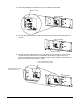
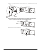
7 Tilt the computer 2 serial panel and pull it outside the cabinet. As you pull the panel out, flip it so the RJ11-6 (RJ12) connectors remain inside the cabinet. The front of the panel should face you. Rear of Cab inet Tilt the panel diagonally 8 Pull it outside the cabinet Partially tighten the four screws that hold the computer 2 serial panel in place. Once all of the screws are in position, fully tighten them. Avoid over-tightening the screws.
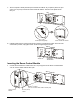
2 Bundle any excess cable, fasten it with the supplied tie wrap, and clip off any excess tie-wrap length. Rear of Cab ine Th is de Ca u 1 5 o v ice co mp lie se ha f is su t h e FCC a cc r mfu s wit b je ct l in ep t h r to th u le s. O p p a rt in te rf a ny i nt er te r fe re n e fo e f er ce , e re n ce llo w in ra ti on th a t e n ce r e a n d (2 ) g tw Th is ce m ay d e vic o c a us iv ed , in e mu cl e un st de s ir ud in g ed o p e r at io n.
Updating the Control Panel Firmware The procedure for updating the control panel firmware varies depending on the last four digits of the serial number on your 3000i. You’ll find serial number labels in two places: on the patch panel at the rear of the cabinet and inside the right-hand door on the front of the cabinet. Last Four Digits of the Serial No.
2 Reach inside the cabinet, behind the front panel. Lift the serial-controller metal housing up and then back to release it from the keyholes on the panel. 3 Carefully lower the serial controller through the opening in the front panel. The cables should remain connected to the serial controller. 4 Disconnect the I2C control panel flash cable from the vertical jack on the serial controller.
6 Reach inside the cabinet and attach the serial controller metal housing to the inside of the front panel. To do this, fit the two partially inserted screws on the metal housing into the keyholes on the front panel. NOTE: Avoid pinching any of the cables between the metal housing and the cabinet. Connecting the I2C Control Panel Flash Cable (Serial No.
3 Carefully lower the serial controller through the opening in the front panel. The cables should remain connected to the serial controller. You’ll notice that the I2C control panel flash cable is bundled with the DB9 serial cable. 4 Using cutting pliers or wire cutters, cut the tie wraps as required to free the control panel flash cable. 5 Connect this cable to the vertical jack on the serial controller.
2 Connect the DB9F end of a DB9F/custom cable to the Control port on the Room Control Module. This cable isn’t supplied by SMART Technologies. It’s usually supplied by the thirdparty room control vendor. NOTE: Do not use an off-the-shelf DB9 null-modem cable to connect the SMART Room Control Module to a third-party room-control system, as the DTR/DSR pin will cause the system to malfunction. Rear of Ca bi net T his devi cecompl pa e i s w ti h rt 1 5of th e FC C r ul C i O per at o es.
2 Open the WBDiag application as follows: a On the Boards tab, click the Log button. The Status Log opens. b Click the Diagnostics button. The WBDiag application opens. 3 Open the port in WBDiag as follows: a There are four numbered COM port buttons on the WBDiag toolbar. Ensure that the correct one for your interactive whiteboard is selected. COM 1 Selected b Click the Open Port button. When the port is successfully opened, an OPEN SUCCEEDED!! message appears.
3 Browse to the hex file and open it. The download process takes approximately 20 to 30 minutes. We recommend that you not disturb this process by performing any work on the laptop or internal computer for the duration of the download. During the download, a series of messages appear. At the end of the download, you will see the following: ATTEMPTING TO PROGRAM THE FIRMWARE ON THE WONDERBAR 010.808 -> WONDERBAR IN BOOTLOADER CODE 011.058 -> WONDERBAR BOOTLOADER VERSION: 3.11 016.
Customer Support SMART’s Technical Support team welcomes your call. However, you may want to contact your local reseller first if you experience problems with any SMART product. SMART’s resellers can readily provide you with quick advice so you can start enjoying the benefits of the Room Control Module for the Rear Projection SMART Board 3000i interactive whiteboard without delay. Contacting SMART Technical Support All SMART software includes free telephone, fax and e-mail support.