P L E A S E T H I N K B E F O R E Y O U P RI N T SMART Board™ 600i4 and D600i4 Interactive Whiteboard Systems Configuration and User’s Guide
Product Registration If you register your SMART product, we’ll notify you of new features and software upgrades. Register online at www.smarttech.com/us/Product+Registration. Keep the following information available in case you need to contact SMART Technical Support.
Important Information Read This Section First Before you install and use your SMART Board™ 600i4 or D600i4 interactive whiteboard system, read and understand the safety warnings and precautions in this user’s guide and the included warnings document. These safety warnings and precautions describe the safe and correct operation of your interactive whiteboard system and its accessories, helping you to prevent injuries and equipment damage.
ii | IM P O RT A NT I NF O R M A TI O N Safety Warnings, Cautions and Important Information WARNINGS – GENERAL • Failure to follow the installation instructions included with your interactive whiteboard system, or found in this guide, can result in personal injury or product damage. • To reduce the risk of fire or electric shock, do not expose any component of your interactive whiteboard system to rain or moisture.
ii i | IM P O RT A NT I NF O R MA TI O N • There are no user-serviceable parts inside the pen tray. Only qualified personnel should disassemble the pen tray’s printed circuit boards, and this procedure must be done with proper electrostatic discharge (ESD) protection. WARNINGS – PROJECTOR • Do not stare (or allow children to stare) directly into the projector’s beam of light. Instruct children not to look in the direction of this beam of light.
iv | IM P O RT A NT I NF O R M A TI O N • This projector detects its remaining lamp life. Replace the lamp when a lamp life warning message appears. If you continue to use the projector after the replacement message appears, the lamp can shatter or burst, scattering glass throughout the projector. • If the lamp has shattered or burst: • • – Call your authorized SMART reseller for instructions. Do not attempt to replace the lamp. – Do not touch the glass fragments because they can cause injury.
v | IM P O RT A NT I NF O R MA TI O N • When returning the projector to the boom, replace all of the screws that you removed when you removed the projector. Failure to do so can result in the projector falling from the boom, causing personal injury or product damage. • To reduce the risk associated with a leaking battery in your projector’s remote control: – Use only the specified coin-cell type battery.
vi | IM P O RT A NT I NF O R M A TI O N • Do not block the projector’s ventilation slots and openings. • Avoid turning off the projector during the lamp ignition phase because this can lead to premature lamp failure. Keep the projector lamp on for a minimum of 15 minutes before turning it off to preserve the lamp life. • In a high altitude location over 6000' (1829 m), where the air is thin and cooling efficiency is reduced, use the projector with the fan mode set to High.
vi i | IM P O RT A NT I NF O R MA TI O N IMPORTANT • Use the installation instructions included in the SMART UF65 or SMART UF65w projector boom box to install your system. Do not use the instructions in your SMART Board interactive whiteboard box. • Make sure that an electrical socket is near to your SMART product and remains easily accessible during use. • Using the SMART UF65 or SMART UF65w projector system near a TV or radio could cause interference to the images or sound.
vi ii | IM P O RT A NT I NF O R M A TI O N
Contents Important Information ..............................................................................................i Read This Section First ....................................................................................i Safety Warnings, Cautions and Important Information ....................................ii 1 About Your Interactive Whiteboard System .......................................................... 1 SMART Board 600i4 or D600i4 Interactive Whiteboard System Features .....
x | CO N T EN TS Securing the Projector to the Boom ....................................................... 19 Installing SMART Software........................................................................... 19 3 Using Your Interactive Whiteboard System ........................................................ 21 Using Your Remote Control.......................................................................... 22 Installing the Remote Control Battery..................................................
xi | CO N T EN TS Additional Composite Video Source Controls ........................................ 48 Audio Output Controls ............................................................................ 49 Network Controls.................................................................................... 50 System Controls ..................................................................................... 51 Simple Network Management Protocol (SNMP)...........................................
xi i | CON T EN TS Resolving Image Issues ......................................................................... 72 Accessing the Service Menu ........................................................................ 76 Retrieving Your Password...................................................................... 76 Resetting the Projector........................................................................... 76 6 Maintaining Your Interactive Whiteboard System ......................................
xi ii | C CON T EN TS Hardware Environmental Compliance............................................................... 101 Waste Electrical and Electronic Equipment Regulations (WEEE Directive)101 Restriction of Certain Hazardous Substances (RoHS Directive) ................ 101 Batteries...................................................................................................... 101 Packaging ...................................................................................................
xi v | CON T EN TS
Chapter 1 About Your Interactive Whiteboard System Your SMART Board 600i4 or D600i4 interactive whiteboard system combines the wall-mounted, short-throw SMART UF65 or SMART UF65w projector system with a SMART Board 600 or D600 series interactive whiteboard. Refer to these topics to learn more about the features of your SMART Board 600i4 or D600i4 interactive whiteboard system and for information about product parts and accessories.
2 | CH A P T E R 1 – A BO UT Y O UR I NT ER ACT I V E W H I T E B O A R D S Y S T E M SMART Board 600i4 or D600i4 Interactive Whiteboard System Features Your SMART Board 600i4 or D600i4 interactive whiteboard system uses the SMART UF65 or SMART UF65w short-throw, high-offset projector. Although the projector’s basic operation is the same as in earlier models, SMART made many improvements to make the SMART Board 600i4 or D600i4 interactive whiteboard system easier to install and use.
3 | CH A P T E R 1 – A BO UT Y O UR I NT ER ACT I V E W H I T E B O A R D S Y S T E M Interactive Whiteboard Features Your SMART Board 600 or D600 series interactive whiteboard includes many features of earlier SMART Board interactive whiteboards, such as a resistive touch screen and a pen tray. The SMART Board 600 or D600 series performs best with the SMART UF65 or SMART UF65w projector because of its exceptional color performance and input response.
4 | CH A P T E R 1 – A BO UT Y O UR I NT ER ACT I V E W H I T E B O A R D S Y S T E M SMART UF65 or SMART UF65w Projector System Features The SMART UF65 or SMART UF65w projector system includes a short-throw projector for use with SMART Board 600 or D600 series interactive whiteboards, an extended control panel (ECP) and a sturdy support system for many different environments.
5 | CH A P T E R 1 – A BO UT Y O UR I NT ER ACT I V E W H I T E B O A R D S Y S T E M Extended Control Panel (ECP) Your system’s fully-labeled ECP attaches elegantly to your interactive whiteboard’s bottom frame. The ECP features controls for power, source selection and volume adjustment, as well as an integrated USB hub that enables you to switch seamlessly between two connected computers.
6 | CH A P T E R 1 – A BO UT Y O UR I NT ER ACT I V E W H I T E B O A R D S Y S T E M NOTE Some of SMART’s older pens aren’t designed to reflect infrared light and the pen tray sensors might not detect them reliably. TIP Wrap light-colored tape around a substitute pen to improve the reflection of infrared light and help with tool detection. Eraser The eraser resembles a rectangular chalkboard eraser.
Chapter 2 Additional Details for Installing Your Interactive Whiteboard System Consult the included SMART Board 600i4 or D600i4 interactive whiteboard system installation document for instructions on how to install your product and use the mounting template and extended control panel (ECP). IMPORTANT Use the instructions included with your SMART UF65 or SMART UF65w projector system to install your interactive whiteboard, projector and ECP.
8 | CH A P T E R 2 – A DD IT IO N A L DET A I LS F O R INS T A LL IN G Y O U R I N T E R A C T I V E W H I T E BO A R D S Y S T E M Environmental Requirements Before installing your SMART Board 600i4 or D600i4 interactive whiteboard system, review the following environmental requirements. CAUTION • Do not operate this unit immediately after moving it from a cold location to a warm location.
9 | CH A P T E R 2 – A DD IT IO N A L DET A I LS F O R INS T A LL IN G Y O U R I N T E R A C T I V E W H I T E BO A R D S Y S T E M Environmental Requirement Parameter Operating temperature • 41°F to 95°F (5°C to 35°C) from 0' to 6000' (0 m to 1829 m) • 41°F to 86°F (5°C to 30°C) from 6000' to 9800' (1829 m to 2987 m) Storage temperature -40°F to 122°F (-40°C to 50°C) Humidity • 30% to 70% relative humidity, non-condensing • Humidity above 80% might cause slight wrinkling in the screen surface sheet
10 | CH A P T E R 2 – A DD IT IO N A L DET A I LS F O R INS T A LL IN G Y O U R I N T E R A C T I V E W H I T E BO A R D S Y S T E M Choosing an Installation Location Choose a location for your SMART Board 600i4 or D600i4 interactive whiteboard system that’s far from bright light sources, such as windows or strong overhead lighting. Bright light sources can cause distracting shadows on your interactive whiteboard and can reduce the contrast of the projected image.
11 | CH A P T E R 2 – A DD IT IO N A L DET A I LS F O R INS T A LL IN G Y O U R I N T E R A C T I V E W H I T E BO A R D S Y S T E M Routing the Cables When connecting cables from the SMART UF65 projector to SMART Board 660, 680 and D680 interactive whiteboards, make sure that all cables pass along the top of your SMART Board interactive whiteboard’s wall-mounting bracket, and then down the right side of your interactive whiteboard.
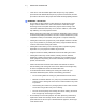
12 | CH A P T E R 2 – A DD IT IO N A L DET A I LS F O R INS T A LL IN G Y O U R I N T E R A C T I V E W H I T E BO A R D S Y S T E M SMART UF65 or SMART UF65w Projector Connection Diagram You can connect a variety of peripheral devices to your projector, including DVD players, VCRs, document cameras, digital cameras and high-definition sources, as well as peripheral device outputs, such as a secondary projector or a flat-panel display and powered speakers.
13 | CH A P T E R 2 – A DD IT IO N A L DET A I LS F O R INS T A LL IN G Y O U R I N T E R A C T I V E W H I T E BO A R D S Y S T E M 13. VGA1-In connector (PC analog signal/component video input) 14. VGA2-In connector (PC analog signal/component video input) 15. Composite video input connector 16. S-video input connector 17. Audio-L connector (for S-video connector) 18. Audio-R connector (for S-video connector) NOTES • Remove the cable cover to access the connection panel.
14 | CH A P T E R 2 – A DD IT IO N A L DET A I LS F O R INS T A LL IN G Y O U R I N T E R A C T I V E W H I T E BO A R D S Y S T E M Focusing the Image To focus the projected image, use the focus ring, located on the bottom of the SMART UF65 or SMART UF65w projector (when the projector is facing downward). NOTE Ensure that you remove the projector’s plastic lens cover. To focus and adjust the image Rotate the focus ring right or left until the image is in focus.
15 | CH A P T E R 2 – A DD IT IO N A L DET A I LS F O R INS T A LL IN G Y O U R I N T E R A C T I V E W H I T E BO A R D S Y S T E M Correcting Alignment Errors Alignment errors occur when the projected image isn’t perpendicular to the screen.
16 | CH A P T E R 2 – A DD IT IO N A L DET A I LS F O R INS T A LL IN G Y O U R I N T E R A C T I V E W H I T E BO A R D S Y S T E M Tips for Adjusting the Projected Image Refer to these notes when adjusting the projected image as described in the included SMART Board 600i4 and D600i4 Interactive Whiteboard System Installation InstrIuctions. • Project a computer image (set to the proper resolution) while adjusting the image.
17 | CH A P T E R 2 – A DD IT IO N A L DET A I LS F O R INS T A LL IN G Y O U R I N T E R A C T I V E W H I T E BO A R D S Y S T E M Securing the Pen Tray, Interactive Whiteboard and Projector Since you can remove the pen tray without tools, you might want to securely attach it to its brackets. To do this, insert two No. 8/M4 screws (not included) into the holes indicated in the following illustration.
18 | CH A P T E R 2 – A DD IT IO N A L DET A I LS F O R INS T A LL IN G Y O U R I N T E R A C T I V E W H I T E BO A R D S Y S T E M If you already secured your pen tray brackets to the wall, you might need to remove the pen tray before you lock it with a security cable. NOTE You don’t need to wear ESD protection when performing the following procedure. To remove the pen tray 1.
19 | CH A P T E R 2 – A DD IT IO N A L DET A I LS F O R INS T A LL IN G Y O U R I N T E R A C T I V E W H I T E BO A R D S Y S T E M Securing the Projector to the Boom To learn how to secure the SMART UF65 or SMART UF65w projector to the boom, see the included SMART Board 600i4 and D600i4 Interactive Whiteboard System Installation Instructions.
20 | CH A P T E R 2 – A DD IT IO N A L DET A I LS F O R INS T A LL IN G Y O U R I N T E R A C T I V E W H I T E BO A R D S Y S T E M
Chapter 3 Using Your Interactive Whiteboard System This chapter describes the basic operation of your interactive whiteboard system, and also explains how to set up your remote control, retrieve system information, access the projector’s image adjustment options and integrate your interactive whiteboard system with peripheral devices.
22 | CH A P T E R 3 – U SIN G Y O UR IN T ER ACT IV E WH IT EB OARD SY ST EM Using Your Remote Control The SMART UF65 or SMART UF65w projector remote control enables you to access on-screen projector menus and change projector settings. Installing the Remote Control Battery Follow this procedure to use the remote control for the first time or to replace the remote control battery.
23 | CH A P T E R 3 – U SIN G Y O UR IN T ER ACT IV E WH IT EB OARD SY ST EM Remote Control Buttons The projector remote control enables you to access on-screen menus and change projector settings. Use the remote control’s Power button (or the ECP’s Power button) to turn the projector system on or off. You can also use the remote control’s Input button (or the ECP’s Input button) to switch sources on the projector.
24 | CH A P T E R 3 – U SIN G Y O UR IN T ER ACT IV E WH IT EB OARD SY ST EM Number Function 7 (Power) 8 (Enter) Description Turn on or turn off the projector Accept the selected mode or option 9 (Volume Up) Increase the volume 10 (Volume Down) Decrease the volume Adjusting Projector Settings The remote control’s Menu button enables you to access the on-screen display to adjust the projector settings. NOTES • There are no projector menu options on the ECP.
25 | CH A P T E R 3 – U SIN G Y O UR IN T ER ACT IV E WH IT EB OARD SY ST EM Menu Heading Image Adjustment, cont’d Settings Description H-position Moves the projected image’s horizontal position left or right from 0 to 100. NOTE Don’t adjust this option unless you’re advised to by a certified SMART Technical Support Specialist. You can apply these settings only after you make all boom adjustments. Applies to VGA inputs only.
26 | CH A P T E R 3 – U SIN G Y O UR IN T ER ACT IV E WH IT EB OARD SY ST EM Menu Heading Settings Description Audio Volume Increases and decreases the projector’s volume from -20 to 20. Mute On mutes the projector’s audio output. Off turns off mute. Disable Volume Control On disables the projector’s volume control and the ECP’s volume control knob. Off enables the volume control and volume control knob. Closed Captioning On turns on closed captioning. Off turns off closed captioning.
27 | CH A P T E R 3 – U SIN G Y O UR IN T ER ACT IV E WH IT EB OARD SY ST EM Menu Heading Default, cont’d Settings Description Lamp Mode Adjusts lamp brightness to Standard or Economy. Standard displays a high-quality, bright image. Economy increases the lamp life by decreasing the brightness of the image. Auto Power Off (minutes) Sets the length of the auto power off countdown timer between 1 and 240 minutes. The timer begins to count down when the projector no longer receives a video signal.
28 | CH A P T E R 3 – U SIN G Y O UR IN T ER ACT IV E WH IT EB OARD SY ST EM Menu Heading Settings Description Default, cont’d Startup Screen Press Enter to access the startup screen menu. You can then select the type of startup screen (SMART, Capture User Startup Screen or Preview Startup Screen). This screen displays when the projector lamp is starting and an image isn’t displayed. Press Exit to return to the Default menu. • SMART displays the default SMART logo on a blue background.
29 | CH A P T E R 3 – U SIN G Y O UR IN T ER ACT IV E WH IT EB OARD SY ST EM Menu Heading Network Settings Description Network and VGA Out The VGA out and Network features are Off by Status Displays the current network status as Connected, Disconnected or Off. DHCP Displays the status of the network’s Dynamic Host Control Protocol (DHCP) as On or Off. default. Select On to activate these features. • On automatically assigns the DHCP server’s IP address to the projector.
30 | CH A P T E R 3 – U SIN G Y O UR IN T ER ACT IV E WH IT EB OARD SY ST EM Menu Heading Settings Description Language Language Selects language preference. Projector menu support is available in English (default), Brazilian Portuguese, Czech, Danish, Dutch, Finnish, French, German, Greek, Iberian Portuguese, Italian, Korean, Japanese, Norwegian, Polish, Russian, Simplified Chinese, Spanish, Swedish and Traditional Chinese.
31 | CH A P T E R 3 – U SIN G Y O UR IN T ER ACT IV E WH IT EB OARD SY ST EM Using Your Interactive Whiteboard Refer to the SMART Board 600 and D600 series Interactive Whiteboard Installation and User’s Guide for more information on using your interactive whiteboard. When you connect your SMART Board interactive whiteboard system to a computer with SMART Product Drivers and SMART software installed, you can access the software’s full capabilities.
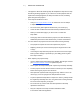
32 | CH A P T E R 3 – U SIN G Y O UR IN T ER ACT IV E WH IT EB OARD SY ST EM ECP Connection Diagram 1 2 3 4 5 7 6 10 8 9 Front View 11 12 13 Rear View Number 1 Function Power and status LED 2 Input 3 Volume control 4 USB B receptacle (for your primary computer) NOTE This USB receptacle is active only when you select VGA1 as the projector input source.
33 | CH A P T E R 3 – U SIN G Y O UR IN T ER ACT IV E WH IT EB OARD SY ST EM Number Function 10 USB B receptacle (for secondary computers such as a laptop) NOTE This USB receptacle is active only when you select VGA2 as the projector input source.
34 | CH A P T E R 3 – U SIN G Y O UR IN T ER ACT IV E WH IT EB OARD SY ST EM Video Format Compatibility Both the SMART UF65 and SMART UF65w projectors have a native video format and various video format compatibility modes. You can change image appearances for certain formats and compatibilities. Native Video Format The following table lists the native VESA RGB video formats for the SMART UF65 and SMART UF65w projector.
35 | CH A P T E R 3 – U SIN G Y O UR IN T ER ACT IV E WH IT EB OARD SY ST EM Resolution Mode Aspect Ratio Refresh Rate (Hz) “Match Input” Appearance 1024 x 768 XGA 60 4:3 60.004 Full screen 1024 x 768 XGA 70 4:3 70.069 Full screen 1024 x 768 XGA 75 4:3 75.029 Full screen 1024 x 768 XGA 85 4:3 84.997 Full screen 1024 x 768 MAC 19" 4:3 74.7 Full screen 1152 x 864 SXGA1 75 4:3 75 Full screen 1280 x 768 SXGA1 75 1.
36 | CH A P T E R 3 – U SIN G Y O UR IN T ER ACT IV E WH IT EB OARD SY ST EM Resolution Mode Aspect Ratio Refresh Rate (Hz) “Match Input” Appearance 832 × 624 MAC 16" 4:3 74.55 Pillarbox 1024 × 768 XGA 60 4:3 60.004 Pillarbox 1024 × 768 XGA 70 4:3 70.069 Pillarbox 1024 × 768 XGA 75 4:3 75.029 Pillarbox 1024 × 768 XGA 85 4:3 84.997 Pillarbox 1024 × 768 MAC 19" 4:3 74.7 Pillarbox 1152 × 864 SXGA 75 4:3 75 Pillarbox 1280 × 768 WXGA 60 1.
37 | CH A P T E R 3 – U SIN G Y O UR IN T ER ACT IV E WH IT EB OARD SY ST EM SMART UF65w Projector Signal Format Aspect Horizontal Vertical Ratio Frequency (kHz) Frequency (Hz) “Match Input” Appearance 480i (525i) 4:3 15.73 59.94 Full screen 480p (525p) 4:3 31.47 59.94 Full screen 576i (625i) 5:4 15.63 50 Pillarbox 576p (625p) 5:4 31.25 50 Pillarbox 720p (750p) 16:9 45 59.94 Letterbox 720p (750p) 16:9 37.5 50 Letterbox 1080i (1125i) 16:9 33.75 59.
38 | CH A P T E R 3 – U SIN G Y O UR IN T ER ACT IV E WH IT EB OARD SY ST EM SMART UF65w Projector Video Mode Aspect Ratio Horizontal Frequency (kHz) Vertical Frequency (Hz) Color Signal (MHz) NTSC 4:3 15.73 59.94 3.58 PAL 4:3 15.63 50 4.43 SECAM 4:3 15.63 50 4.25 and 4.41 PAL-M 4:3 15.73 59.94 3.58 PAL-N 4:3 15.63 50 3.58 PAL-60 4:3 15.73 59.94 4.43 NTSC 4.43 4:3 15.73 59.94 4.
Chapter 4 Remotely Managing Your Interactive Whiteboard System This chapter includes detailed instructions on how to set up your computer or room control system to remotely manage your SMART Board 600i4 or D600i4 interactive whiteboard system settings through an RS-232 serial interface.
40 | CH A P T E R 4 – R E MO T E L Y M A N A G IN G Y O U R IN T ERAC T IVE WH IT EBOA RD SYS TE M Connecting Your Room Control System to the SMART UF65 or SMART UF65w Projector By connecting a computer or room control system to the SMART UF65 or SMART UF65w projector’s RS-232 serial interface, you can select video inputs, start up or shut down your interactive whiteboard system and request information such as projector lamp use, current settings and network addresses.
41 | CH A P T E R 4 – R E MO T E L Y M A N A G IN G Y O U R IN T ERAC T IVE WH IT EBOA RD SYS TE M NOTES To configure your computer’s serial interface • Asynchronous mode is disabled by default in the projector. • All commands should be in ASCII format. Terminate all commands with a carriage return. • All responses from the projector are terminated with a command prompt. Wait until you receive the command prompt, indicating that the system is ready for another command, before proceeding.
42 | CH A P T E R 4 – R E MO T E L Y M A N A G IN G Y O U R IN T ERAC T IVE WH IT EBOA RD SYS TE M Projector Programming Commands Projector Powerstate Controls The SMART UF65 or SMART UF65w projector responds to commands only at certain power levels and times. There are five projector power states: • Powering (startup) • On (operating) • Cooling • Confirm off • Idle Command Inventory The SMART UF65 or SMART UF65w projector responds to the commands in the tables on the following pages.
43 | CH A P T E R 4 – R E MO T E L Y M A N A G IN G Y O U R IN T ERAC T IVE WH IT EBOA RD SYS TE M See the following example for adjusting projector brightness: >get brightness brightness=55 >set brightness=65 brightness=65 >set brightness+5 brightness=70 >set brightness-15 brightness=55 Video Source Specification Values You can use the source input field described on page 45 in a command to set an absolute value or adjustment value to a source other than the active source.
44 | CH A P T E R 4 – R E MO T E L Y M A N A G IN G Y O U R IN T ERAC T IVE WH IT EBOA RD SYS TE M Powerstate Controls These commands turn on or turn off the projector and request the projector’s current powerstate. The projector’s powerstate determines whether or not certain commands are available at that time. These settings are always available, even when the projector is off.
45 | CH A P T E R 4 – R E MO T E L Y M A N A G IN G Y O U R IN T ERAC T IVE WH IT EBOA RD SYS TE M Source Selection Controls These commands switch input sources. The source type determines which commands can be accepted. Command Response Available When Powered Off get input input=[field] yes set input [field] input=[field] no Source Selection Response Field Description Field Description VGA1 Switches source to the VGA 1 input connector. VGA2 Switches source to the VGA 2 input connector.
46 | CH A P T E R 4 – R E MO T E L Y M A N A G IN G Y O U R IN T ERAC T IVE WH IT EBOA RD SYS TE M Command Response get blue blue=[current blue color setting] get cyan cyan=[current cyan color setting] get magenta magenta=[current magenta color setting] get yellow yellow=[current yellow color setting] get videofreeze videofreeze=[current video freeze setting] Source Control Commands These commands control the appearance of your source.
47 | CH A P T E R 4 – R E MO T E L Y M A N A G IN G Y O U R IN T ERAC T IVE WH IT EBOA RD SYS TE M Additional VGA Source Controls Your VGA source supports all the general source controls described on page 45, as well as the commands listed in this section. These settings are unavailable when the projector is off, or when the VGA sources are disconnected. NOTE Some of these commands are invalid with composite video sources.
48 | CH A P T E R 4 – R E MO T E L Y M A N A G IN G Y O U R IN T ERAC T IVE WH IT EBOA RD SYS TE M Additional Composite Video Source Controls Your composite video source supports all the general source controls described on the previous page, as well as the commands listed in this section. These settings are unavailable when the projector is off, or when the composite video source is disconnected. NOTE Some of these commands are invalid with VGA video sources.
49 | CH A P T E R 4 – R E MO T E L Y M A N A G IN G Y O U R IN T ERAC T IVE WH IT EBOA RD SYS TE M Audio Output Controls These commands control your projector’s audio output to your audio system (not included). Audio output controls aren’t defined by the video source. These settings are unavailable when the projector is off. Audio Output Information Commands These commands inform you of the current audio output settings.
50 | CH A P T E R 4 – R E MO T E L Y M A N A G IN G Y O U R IN T ERAC T IVE WH IT EBOA RD SYS TE M Network Controls These commands control your projector’s network status and settings. These settings are always available, even when the projector is off. Network Information Commands These commands inform you of the current network settings.
51 | CH A P T E R 4 – R E MO T E L Y M A N A G IN G Y O U R IN T ERAC T IVE WH IT EBOA RD SYS TE M System Controls Enables you to switch system settings and access system information. System Information Commands (Active) These commands inform you of the current system settings. These commands are unavailable when the projector is off.
52 | CH A P T E R 4 – R E MO T E L Y M A N A G IN G Y O U R IN T ERAC T IVE WH IT EBOA RD SYS TE M System Information Commands (Passive) These commands inform you of the current system settings. These commands are always available, even when the projector is off.
53 | CH A P T E R 4 – R E MO T E L Y M A N A G IN G Y O U R IN T ERAC T IVE WH IT EBOA RD SYS TE M Command Command Target Range Response set projectionmode [target] =front projectionmode=[target] =ceiling =rear =rear ceiling set startupscreen [target] =smart startupscreen=[target] =usercapture =preview set language [target] =Brazilian Portuguese language=[target] =Czech =Danish =Dutch =English =Finnish =French =German =Greek =Iberian Portuguese =Italian =Korean =Japanese =Norwegian =Polish =R
54 | CH A P T E R 4 – R E MO T E L Y M A N A G IN G Y O U R IN T ERAC T IVE WH IT EBOA RD SYS TE M Command Command Target Range Response set locationinfo [description] Enter a descriptor no more than 16 characters long. locationinfo=[description] set contactinfo [description] Enter a descriptor no more than 16 characters long.
55 | CH A P T E R 4 – R E MO T E L Y M A N A G IN G Y O U R IN T ERAC T IVE WH IT EBOA RD SYS TE M Simple Network Management Protocol (SNMP) SMART UF65 and SMART UF65w projectors support a list of SNMP commands as described in the management information base (MIB) file. The SNMP agent supports SNMP version 1. Upload the MIB file to your SNMP management system application, and then use it as described in your application’s user guide.
56 | CH A P T E R 4 – R E MO T E L Y M A N A G IN G Y O U R IN T ERAC T IVE WH IT EBOA RD SYS TE M Home The Home menu page displays basic projector information and enables you to select the on-screen display language. Submenu Setting Description Language Displays language options Projector Information Displays current projector information Control Panel This menu enables you to manage the projector audio and video status, alerts and appearances, using an Internet browser.
57 | CH A P T E R 4 – R E MO T E L Y M A N A G IN G Y O U R IN T ERAC T IVE WH IT EBOA RD SYS TE M Submenu Setting Description Display Mode Adjusts the display output to SMART Presentation, Bright Room, Dark Room, sRGB and User modes so you can project images from various sources with consistent color performance: • SMART Presentation is recommended for color fidelity. • Bright Room and Dark Room are recommended for locations with those conditions. • sRGB provides standardized accurate color.
58 | CH A P T E R 4 – R E MO T E L Y M A N A G IN G Y O U R IN T ERAC T IVE WH IT EBOA RD SYS TE M Submenu Setting Description Lamp Reminder Select On to show or Off to hide the lamp replacement reminder when it appears. This reminder appears 100 hours before the recommended lamp replacement. Lamp Mode Adjusts lamp brightness to Standard or Economy. Standard displays a high-quality, bright image. Economy increases the lamp life by decreasing the brightness of the image.
59 | CH A P T E R 4 – R E MO T E L Y M A N A G IN G Y O U R IN T ERAC T IVE WH IT EBOA RD SYS TE M Submenu Setting Description Startup Screen Selects the type of startup screen to SMART or User. The SMART screen is the default SMART logo on a blue background. The User screen uses the saved picture from the Capture User Startup Screen function. Video Mute Turns the video mute setting On or Off. Select On to hide the display and Off to show it again.
60 | CH A P T E R 4 – R E MO T E L Y M A N A G IN G Y O U R IN T ERAC T IVE WH IT EBOA RD SYS TE M 3D Settings This menu allows you to enable or disable 3D image display and set the format. Submenu Setting Description 3D On/Off Turns the 3D feature On or Off. 3D Invert Selects the 3D Invert setting (L-R or R-L). • L-R displays visual data for the left eye first. • R-L displays visual data for the right eye first. 3D Format Selects the 3D format (Interleaved or Under-over).
61 | CH A P T E R 4 – R E MO T E L Y M A N A G IN G Y O U R IN T ERAC T IVE WH IT EBOA RD SYS TE M Submenu Setting Description Location Displays the projector’s location (maximum 16 characters). Contact Displays the contact name or number for projector support (maximum 16 characters). SNMP Turns the SNMP’s MIB function On or Off. Read-Only Community This option is a password sent with each SNMP Get-Request and enables access to the device. NOTE The default for Read-Only Community is public.
62 | CH A P T E R 4 – R E MO T E L Y M A N A G IN G Y O U R IN T ERAC T IVE WH IT EBOA RD SYS TE M Submenu Setting Description Outgoing SMTP server Defines the Simple Mail Transfer Protocol (SMTP) server. Username Defines the SMTP server user name. Password Defines the SMTP server password. Alert Condition Sends e-mail alerts whenever Lamp Warning, Low Lamp Life, Temperature Warning and Fan Lock conditions occur. Select the settings you want, and then press Submit.
Chapter 5 Troubleshooting Your Interactive Whiteboard System This chapter provides basic troubleshooting information for your interactive whiteboard system. For issues not covered in this section, contact your authorized SMART reseller or consult the SMART Support website.
64 | CH A P T E R 5 – T R O U B L E S H O O T I N G Y O U R IN TE RAC T IVE W H I T E B O A R D SYS TE M System Status and Warning Lights This section describes your SMART Board 600i4 or D600i4 interactive whiteboard system’s three status and warning light regions and their patterns. Refer to these tables to troubleshoot your interactive whiteboard, ECP or projector.
65 | CH A P T E R 5 – T R O U B L E S H O O T I N G Y O U R IN TE RAC T IVE W H I T E B O A R D SYS TE M Integrated Interactive Whiteboard Ready Light Status Your interactive whiteboard’s LED Ready light is in the lower-right corner of the frame. This light indicates the operational state of the controller module.
66 | CH A P T E R 5 – T R O U B L E S H O O T I N G Y O U R IN TE RAC T IVE W H I T E B O A R D SYS TE M Interactive Whiteboard Ready Light Status Flashing green Your interactive whiteboard is on and communicating with your computer, but it’s in Mouse mode. Confirm that SMART Product Drivers is installed on your computer. Flashing amber Your interactive whiteboard system is turning on, is in service mode or has detected a firmware error.
67 | CH A P T E R 5 – T R O U B L E S H O O T I N G Y O U R IN TE RAC T IVE W H I T E B O A R D SYS TE M Power LED Service LED Message (Green/Amber) (Red) Off Solid red The projector has a fan issue. The projector might shut down automatically. See The “Fan Failure” Message Appears on page 68 to troubleshoot the projector. Off Solid red The projector has a color wheel issue. See The “Color Wheel Failure” Message Appears on page 69 to troubleshoot the projector.
68 | CH A P T E R 5 – T R O U B L E S H O O T I N G Y O U R IN TE RAC T IVE W H I T E B O A R D SYS TE M The “Projector Overheated” Message Appears If the “Projector Overheated” indicator message appears and the projector turns off during use, one of the following issues is occurring: To resolve the “Projector Overheated” error • The projector is overheating internally. The projector can overheat because of blocked air vents or an internal temperature over 131°F (55°C).
69 | CH A P T E R 5 – T R O U B L E S H O O T I N G Y O U R IN TE RAC T IVE W H I T E B O A R D SYS TE M The “Color Wheel Failure” Message Appears If the “Color Wheel Failure” error message appears and the projector turns off during use, the projector has a color wheel issue. To resolve the “Color Wheel Failure” error 1. Turn off the projector, and then wait 15 minutes for it to cool down. 2. Disconnect the power cable from the power outlet. Wait a minimum of 60 seconds. 3.
70 | CH A P T E R 5 – T R O U B L E S H O O T I N G Y O U R IN TE RAC T IVE W H I T E B O A R D SYS TE M The Ready Light Isn’t Lit If your Ready light isn’t lit, one of the following issues is occurring: To resolve your unlit Ready light issue • There was a power outage or a power surge. • A circuit breaker or a safety switch was tripped. • The projector isn’t connected to the power source. • The projector has an internal problem. 1.
71 | CH A P T E R 5 – T R O U B L E S H O O T I N G Y O U R IN TE RAC T IVE W H I T E B O A R D SYS TE M Resolving Audio Issues The projector doesn’t have integrated speakers, but you can connect an audio system to the audio output connector in the projector’s connection panel. If no sound is coming from your audio system, perform the following procedure. To resolve audio issues 1.
72 | CH A P T E R 5 – T R O U B L E S H O O T I N G Y O U R IN TE RAC T IVE W H I T E B O A R D SYS TE M Resolving Image Issues Computers, peripherals, source inputs and their connection cables may not be set up correctly to transmit their signals to your SMART Board interactive whiteboard system. Refer to Video Format Compatibility on page 34 and the following section to help resolve these issues.
73 | CH A P T E R 5 – T R O U B L E S H O O T I N G Y O U R IN TE RAC T IVE W H I T E B O A R D SYS TE M No Projected Image If the projector displays no image at all, and the ECP, interactive whiteboard and projector power lights aren’t on, perform the following procedure. To resolve projected image issues 1. Ensure that the power cord is connected to the power outlet. 2.
74 To change the monitor display | CH A P T E R 5 – T R O U B L E S H O O T I N G Y O U R IN TE RAC T IVE W H I T E B O A R D SYS TE M 1. Click Advanced Properties. 2. On the Monitor tab, click Change. 3. Click Show all devices, and then select Standard monitor types from the list. 4. In the Models list, select the resolution you need. 5. Verify that the resolution setting of the monitor display is lower than or equal to 1024 × 768 (SMART UF65 projector) or 1280 × 800 (SMART UF65w projector).
75 | CH A P T E R 5 – T R O U B L E S H O O T I N G Y O U R IN TE RAC T IVE W H I T E B O A R D SYS TE M Your Image Has a Vertical Flickering Bar If the projector displays a vertical flickering bar, you may have different frequency settings set on your input source. IMPORTANT Write down your setting values before adjusting any of the settings in the following procedure. To resolve the vertical flickering bar issue 1. Adjust the Frequency setting in the on-screen display. See page 24. 2.
76 | CH A P T E R 5 – T R O U B L E S H O O T I N G Y O U R IN TE RAC T IVE W H I T E B O A R D SYS TE M Accessing the Service Menu CAUTION • To prevent tampering or unintentional changes, only system administrators should access the service menu. Do not share the service menu access code with casual users of your interactive whiteboard system. • Do not adjust any settings in the service menu other than those listed in the following procedures.
Chapter 6 Maintaining Your Interactive Whiteboard System This chapter includes methods for preventing damage to and properly cleaning your SMART Board 600i4 or D600i4 interactive whiteboard system.
78 | CH A P T E R 6 – M A I N T A I NI NG Y O U R I NT E R A C T I V E W H I TE BO A R D S Y S T E M Preventing Damage to Your Interactive Whiteboard Although your SMART Board interactive whiteboard’s surface is very durable, take the following precautions to prevent damage to the interactive screen and other components. • Don’t use sharp or pointed objects, such as ballpoint pens or pointers, as writing tools. • Don’t use abrasive erasers or harsh chemicals when cleaning your product.
79 | CH A P T E R 6 – M A I N T A I NI NG Y O U R I NT E R A C T I V E W H I TE BO A R D S Y S T E M TIP For information on disinfecting your interactive whiteboard, see Disinfecting Your SMART Board Interactive Whiteboard. Removing Permanent Marker Ink Stains You can use a high-odor dry-erase marker to remove marks from a permanent marker, because dry-erase ink contains solvents that can remove permanent ink.
80 | CH A P T E R 6 – M A I N T A I NI NG Y O U R I NT E R A C T I V E W H I TE BO A R D S Y S T E M Cleaning the SMART UF65 or SMART UF65w Projector WARNING Cleaning a boom-mounted projector may result in a fall and injury. Use caution when climbing a ladder. CAUTION • Before you clean the SMART UF65 or SMART UF65w projector, press the Power button twice on the ECP or remote control to put the system into Idle mode, and then allow the lamp to cool for 30 minutes.
81 | CH A P T E R 6 – M A I N T A I NI NG Y O U R I NT E R A C T I V E W H I TE BO A R D S Y S T E M Cleaning the Lamp Module and Projector Vents This section provides instructions for using a vacuum cleaner to remove accumulated dust from the SMART UF65 or SMART UF65w projector’s lamp module, vents and slots. SMART recommends cleaning your projector every six months. If your projector is regularly exposed to dust, clean it every three months.
82 | CH A P T E R 6 – M A I N T A I NI NG Y O U R I NT E R A C T I V E W H I TE BO A R D S Y S T E M Removing the Projector from the Boom Before you can access the projector lamp module, you must remove the projector from the boom. WARNING Two people are required to remove the projector from the boom. To remove the projector from the boom 1. Turn off the projector by pressing the Power button twice on the remote control or ECP to put the system into Idle mode. 2.
83 | CH A P T E R 6 – M A I N T A I NI NG Y O U R I NT E R A C T I V E W H I TE BO A R D S Y S T E M 6. Using a Phillips® No. 2 screwdriver, remove the single screw on the bracket. Place the screw in a safe place. CAUTION The projector can fall if you move it after you remove this screw. 7. Using two hands, carefully unhook and remove the projector from the projector boom. 8. Lay the projector flat on your work area with the warning lights facing upward.
84 | CH A P T E R 6 – M A I N T A I NI NG Y O U R I NT E R A C T I V E W H I TE BO A R D S Y S T E M Accessing the Lamp Module To access the lamp module, remove the lamp cover, and then remove the lamp from the projector. To remove the lamp cover and lamp module 1. Pull off the outer lamp cover with your finger and set it aside. 2. Using a Phillips No. 2 screwdriver, loosen the two screws on the inner lamp module. The screws remain captive inside the lamp module.
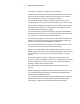
85 | CH A P T E R 6 – M A I N T A I NI NG Y O U R I NT E R A C T I V E W H I TE BO A R D S Y S T E M 3. Pull up on the lamp module’s handle, and then remove the lamp. 4. Gently place the lamp module on your work area with the handle facing downward. Vacuuming the Lamp Module and Projector Vents After you remove the lamp cover and lamp module, vacuum the lamp module and projector vents. To vacuum the lamp module and projector vents 1.
86 | CH A P T E R 6 – M A I N T A I NI NG Y O U R I NT E R A C T I V E W H I TE BO A R D S Y S T E M 2. Thoroughly vacuum the three top vents, the lamp slot and the I/O panel vent on the projector as indicated in the following images for 10 seconds each. Vents Lamp Slot I/O Panel Vent Replacing the Lamp Module and Lamp Cover After you vacuum the lamp module and projector vents, replace the lamp module and cover. To replace the lamp module and lamp cover 1.
87 | CH A P T E R 6 – M A I N T A I NI NG Y O U R I NT E R A C T I V E W H I TE BO A R D S Y S T E M Replacing the Projector When you’ve replaced the lamp module and lamp cover, replace the projector on the boom. WARNING Two people are required to replace the projector. To replace the projector on the boom 1. Using two hands, put the projector back on the boom by aligning the hooks with the slots on the projector. CAUTION Hold the projector firmly when reattaching it to the boom. 2.
88 | CH A P T E R 6 – M A I N T A I NI NG Y O U R I NT E R A C T I V E W H I TE BO A R D S Y S T E M 3. If applicable, replace your optional projector padlock. 4. Replace the projector cover on the top of the boom. 5. Without applying pressure to the boom, replace and tighten the cover screw until it’s secure. 6. Connect all cables to the projector, and then attach the cable cover. 7. Connect the power cable to a power outlet.
89 | CH A P T E R 6 – M A I N T A I NI NG Y O U R I NT E R A C T I V E W H I TE BO A R D S Y S T E M 8. Confirm that the projector is operating and that the lamp module is correctly installed by pressing the Power button once on the remote control or ECP, and then waiting for the projector to turn on completely. The ECP’s power light turns solid green when the system starts. 9. Wait five minutes for the projector to warm up.
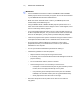
90 | CH A P T E R 6 – M A I N T A I NI NG Y O U R I NT E R A C T I V E W H I TE BO A R D S Y S T E M Locating Your Projector Serial Number The serial number on the SMART UF65 or SMART UF65w projector is located on the top mounting plate (the side away from the projector’s lens). Serial Number Location You can also access the serial number through the projector’s on-screen menu. For more information, see “Serial Number” on page 30.
Chapter 7 Replacing the SMART UF65 or SMART UF65w Projector Lamp This chapter provides detailed instructions for replacing the projector’s lamp. • Removing and Replacing the Projector Lamp Module (this page) • Resetting the Lamp Timer on page 94 Removing and Replacing the Projector Lamp Module If a lamp fails, or if a replacement message appears on the SMART UF65 or SMART UF65w projector’s screen, a qualified person can replace the projector lamp module.
92 | CH A P T E R 7 – R E P L A C I N G T H E S M A R T U F 6 5 O R S M A R T U F 6 5 W P R O J E C T O R LA MP You require a Phillips No. 2 screwdriver to perform the following procedure. To remove and replace the projector lamp module 1. Remove the outer lamp cover with your finger and set it aside. 2. Using a Phillips No. 2 screwdriver, loosen the two screws on the inner lamp module. The screws remain captive inside the lamp module. 3. Pull up on the lamp module’s handle, and then remove the lamp.
93 | CH A P T E R 7 – R E P L A C I N G T H E S M A R T U F 6 5 O R S M A R T U F 6 5 W P R O J E C T O R LA MP 4. Put the old lamp in a secure container. Handle the old lamp gently until you recycle or dispose of it. IMPORTANT Recycle or dispose of the lamp module according to your local waste authority. 5. Remove the replacement lamp module from its packaging. CAUTION Do not touch any part of the lamp module except the housing. 6.
94 | CH A P T E R 7 – R E P L A C I N G T H E S M A R T U F 6 5 O R S M A R T U F 6 5 W P R O J E C T O R LA MP Resetting the Lamp Timer After you replace the lamp, you need to access the projector service menu and reset the lamp hour counter. To prevent accidental errors, only a system administrator should perform this procedure. NOTE Always reset the Lamp Hours after you exchange a lamp. Lamp service reminders are based on the current hours of use. To reset the lamp timer 1.
Appendix A Disabling USB Communications Disabling the ECP’s USB Port In some situations, you may need to disable the ECP’s front USB port. Disabling the USB port prevents users from using or saving documents to USB storage devices using the ECP’s front USB receptacle. The other USB receptacles won’t be deactivated since they’re required for your interactive whiteboard and computer connections to function.
96 To remove and cut the case on the ECP | AP PENDI X A – D I S A B L I N G U S B C O M MU N I C A T I O N S 1. Turn off the projector, and then wait 15 minutes for it to cool down. 2. Disconnect the projector’s power cable from the power outlet. 3. While holding the ECP to prevent it from falling, use a Phillips screwdriver to remove the two screws from the bottom of the ECP. Place the screws in a safe place. 4. Remove all cables connected to the ECP. 5.
97 To remove the USB jumper switch | AP PENDI X A – D I S A B L I N G U S B C O M MU N I C A T I O N S 1. Locate the USB jumper behind the jumper cover port. 2. Using needle-nose pliers, pull the jumper from the two connection posts, and then place it on a single post. IMPORTANT Do not discard the jumper. Discarding the jumper makes the USB deactivation difficult to reverse. 3. Insert the USB jumper cover into the USB A port on the front of the ECP. 4. Connect all cables to the ECP.
98 | AP PENDI X A – D I S A B L I N G U S B C O M MU N I C A T I O N S
Appendix B Hardware Environmental Compliance SMART Technologies supports global efforts to ensure that electronic equipment is manufactured, sold and disposed of in a safe and environmentally friendly manner. Waste Electrical and Electronic Equipment Regulations (WEEE Directive) Waste Electrical and Electronic Equipment regulations apply to all electrical and electronic equipment sold within the European Union.
10 0 | AP PENDI X B – HA RD WAR E E NVI RON MEN T AL COM PLI ANC E Packaging Many countries have regulations restricting the use of certain heavy metals in product packaging. The packaging used by SMART Technologies to ship products complies with applicable packaging laws. China’s Electronic Information Products Regulations China regulates products that are classified as EIP (Electronic Information Products).
Appendix C Customer Support Online Information and Support Visit www.smarttech.com/support to view and download user’s guides, how-to and troubleshooting articles, software and more. Training Visit www.smarttech.com/trainingcenter for training materials and information about our training services. Technical Support If you experience difficulty with your SMART product, please contact your local reseller before contacting SMART Technical Support. Your local reseller can resolve most issues without delay.
10 2 | AP PENDI X C – C U S T O M E R S U P PO R T General Inquiries Address SMART Technologies 3636 Research Road NW Calgary, AB T2L 1Y1 CANADA Switchboard +1.403.245.0333 or Toll Free 1.888.42.SMART (U.S./Canada) Fax +1.403.228.2500 E-mail info@smarttech.com Warranty Product warranty is governed by the terms and conditions of SMART’s “Limited Equipment Warranty” that shipped with the SMART product at the time of purchase. Registration To help us serve you, register online at www.smarttech.
Index A absolute and adjustment values, 42 adjusting correcting alignment errors, 15 default settings, 26 focusing the image, 14 image adjustment options, 24 position adjustment options, 24, 25 tips for adjusting the projected image, 16 audio mute, 71 audio system controls, 49 automatically switching source inputs, 26 B batteries, 101 remote control, 22 before installing your system, 10 environmental requirements, 8 blue screen appears, 72 Bright Room mode, 57 C Chinese regulations, 102 cleaning, 78 lens,
10 4 | IN DE X E-mail Alert page, 61 enabling your network port, 70 enabling your VGA out port, 70 environmental compliance, See hardware environmental compliance eraser, 6 European Union regulations, 101 Extended Control Panel (ECP) about, 5 functions, 31 overview, 5 F Fan Lock e-mail alert, 62 fan speed, 59 G general inquiries, 100 H hardware environmental compliance, 101 harness cable (ECP), 5 high definition signals, 36 Home page, 56 I image custom adjustment options, 25, 57 display mode presets,
10 5 | IN DE X P S packaging, 102 Password Settings page, 62 pen tray cleaning, 79 tools, 6 pens, 6 poor image quality, 73 powerstate controls, 44 projector additional VGA controls, 47 audio output controls, 49 cleaning, 80 compatible interactive whiteboards, 3 composite video controls, 48 enabling network port, 70 enabling VGA out port, 70 general source controls, 45 language selection, 56 network controls, 50 password retrieval, 76 powerstate controls, 44 remote control, 5, 22 replacing the lamp modul
10 6 | IN DE X troubleshooting audio system errors, 71 forgotten password, 76 frozen image, 71 image doesn’t appear, 73 laptop image, 74 network connection, 70 Powerbook image, 74 projector reset, 76 projector stops responding, 67 scrolling image, 73 signal loss, 72 unstable image, 74 vertical flickering bar, 75 warning lights, 64 troubleshooting articles, 99 U U.S.
Toll Free 1.866.518.6791 (U.S./Canada) or +1.403.228.5940 www.smarttech.