
User's Manual


5
rev - 12/01/10
123456789
ETD
+
0
-
ID SET RESET
Hard-wire
from
Gate Opener
Power Supply
from
Opener
Battery
#
1
#
2
POWER
RELAY
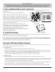
Jumper ON
wireless mode
Jumper OFF
wired mode
HARD-WIRED INSTALLATION
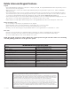
You will need two pairs of 16 gauge (AWG) stranded, direct burial, low voltage wire (RB509), one pair to hard-wire the
communication between the keypad and the gate opener, the other to exend the life of the four “C” batteries. NOTE: The
four “C” batteries are required for reliable operation of the keypad.
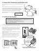
Step 1: Turn the gate opener’s power switch OFF.
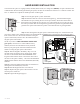
Step 2: Determine how the wires will enter the keypad (e.g., from the back through a
hole drilled in the post; running the wire on the post surface). Drill a hole in the back of
the keypad cover and pull the wire into the cover. Then mount the cover to the post using
the screws provided. Run wire through PVC pipe from the ground to keypad and from the
ground to the opener control board to protect it from lawn mowers or grazing animals.
Step 3: Wire the keypad to the gate opener control board. Strip 3/16” off the ends of one
pair of low voltage wires. Attach the wires to the terminal block marked RELAY on the keypad control board as shown.
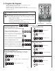
Then connect wire #1 to the CYCLE terminal on the gate
opener control board, and wire #2 to the COM terminal on
the gate opener control board
NOTE: If you have a PRO 1000/2000/SL1000/SL2000
gate opener, connect wire #1 to the WHT accessory
terminal, and wire #2 to the GRN accessory terminal.
Refer to your gate opener instruction manual for more
details on wiring the gate opener control board.
Step 4: Wire the keypad to the battery. Strip 3/16” off
the ends of the second pair of low voltage wires. Attach
the wires to the terminal block marked POWER on the
keypad control board as shown. Connect the other end of
the wires to the opener’s battery: one end to the POSITIVE
(RED) terminal and the other to the NEGATIVE (BLACK)
terminal.
Step 5: Connect the jumper between the two terminals on
the keypad control board (ON) as shown.
Step 6: Slide the keypad into the cover and lock.
Step 7: Replace the gate opener control board cover and
turn the power switch ON.
Step 8: Program the keypad (page 3).
Drill Hole