
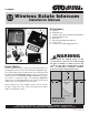
User's Manual


2
rev - 12/01/10
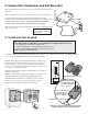
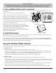
2. Connect the Transformer and Test Base Unit
Step 1: Find a convenient location near an AC outlet to mount or place the
base unit.
Step 2: Plug the transformer into the outlet and connect it to the base unit.
The base unit can be disconnected from the transformer for use in
another location. The battery will last approximately four (4) hours when
unplugged from the transformer. You can turn the base unit OFF to
conserve battery power, however it will not receive a signal.
Step 3: Test the base unit by pressing the CALL button on the keypad. The
base unit will ring.
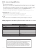
Charge battery for 12 hours
before using the system for
the first time.
POWER
Keypad
Batt Low
Grant Permission
Push To Answer/Talk
End Call
DV 9V
Transformer
110 Vac outlet
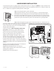
3. Install and Test Keypad
For wireless applications, the keypad must be in line of sight of and no more than 50 ft. away from the gate opener
receiver. Test the keypad range before permanently mounting it.
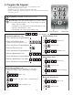
Step 1: At the gate, set the keypad DIP switches to match your
Entry Transmitter’s DIP switch settings. NOTE: If you have not
adjusted your gate opener’s Entry Transmitter from the factory
setting, see the “Personalize Transmitter Settings” section in your
gate opener’s installation manual.
Step 2: Test the keypad using the default Master Code “1234.” It
will activate the gate.
Step 3: Test the keypad range by pressing the CALL button. You
will hear the base unit ringing through the keypad speaker.
Step 4: Mount the keypad cover using the screws provided.
NOTE: a metal housing or metal object can affect range.
Step 5: Slide the keypad into the cover and lock it.
You will need to hard-wire your keypad to the gate opener if you:
• Do NOT have a GTO Entry Transmitter.
• Have a GTO Access Systems GP Series gate opener.
• Live in an area with high radio frequency interference.
Skip to page 5 for instructions.
123456789
ETD
+
0
-
ID SET RESET
If you use this button
to operate gate, put
the 9th DIP Switch
in the “0” position
Dual Button Entry Transmitter
1 2 3 4 5 6 7 8 9
ECE
A23S 12V
ALKALINE BATTERY
+
0
–
LED
Single Button Entry Transmitter
If you use this button
to operate gate, put
the 9th DIP Switch in
the “+” position
Change the Keypad’s DIP Switch Settings NOT
the Entry Transmitter Dip Switch Settings