
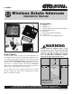
User's Manual


1
rev - 12/01/10
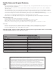
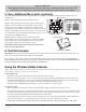
Keypad and Base Unit Overview
Front
Interior
Calling Light:
Turns RED when calling; turns
GREEN when call is answered.
Granted Light:
Turns GREEN when access
permission is granted.
Program Button:
Used to program Entry Codes.
Status Light:
Blinks once when any key is
pressed; provides visual feedback
when programming keypad.
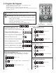
3
DEF
9
WXY
6
MNO
2
0
CALL
4
GHI
7
PRS
1
ABC
8
TUV
5
JKL
Presence
Sensors
123456789
ETD
+
0
-
ID SET RESET
REQUIRES 4 “C”
SIZE BATTERIES
123456789
ETD
+
0
-
ID SET RESET
REQUIRES 4 “C”
SIZE BATTERIES
Relay Output:
Used to connect the keypad to gate
opener control board (hard-wired
installations).
Power Input:
To connect keypad to gate opener power
source (hard-wired installations).
DIP Switches:
Match keypad DIP switch settings to
Entry Transmitter’s DIP switch settings.
Jumper:
OFF: Wireless mode 318 MHz enable.
ON: Relay out (hard-wired installations).
318 MHz disable.
Reset Button:
Press this button for 2 seconds to
program keypad to Master Code default
“1234” (and delete all other codes).
ID Set Button:
Used to sync additional base units with
keypad.
Battery Holder and Cover:
Use 4 “C” batteries.
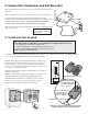
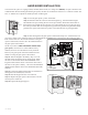
Face
POWER
Keypad
Batt Low
Grant Permission
Push To Answer/Talk
End Call
DV 9V
Power Light:
GREEN: charging; RED: battery
power mode (unplugged from
transformer); Blinking RED: low
battery.
Push To Answer/Talk Button:
To answer call from keypad: press
and hold to talk; release to listen.
Grant Permission Button:
Must be pressed before the person
at the keypad can press any key to
open the gate.
End Call Button:
Terminates the call.
Keypad Battery Indicator
Light:
ON when keypad battery is low.
Power Jack:
Connect transformer to charge the
battery.
ID SET
VOLUME
POWER
OFF
ON
Volume Control:
Controls volume level of speaker.
Battery Access Cover:
Rechargeable 3.6 Volt Ni-MH battery
(included).
ID Set Button:
Used to sync additional base units with
keypad.
ON/OFF Switch:
Turn OFF to conserve battery power.
Bottom
1. Install Keypad and Base Unit Batteries
Step 1: Unlock the bottom of the keypad and separate it from its cover. Remove battery cover and install four “C” batteries
(required, not included). Replace the battery cover.
Step 2: Remove the base unit battery cover using a small phillips head screwdriver. Install the rechargeable Ni-MH battery
(included). Replace battery cover.
ID SET