
PCF8574T Datasheet


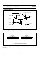

Table Of Contents
- 1 FEATURES
- 2 GENERAL DESCRIPTION
- 3 ORDERING INFORMATION
- 4 BLOCK DIAGRAM
- 5 PINNING
- 6 CHARACTERISTICS OF THE I 2 C-BUS
- 7 FUNCTIONAL DESCRIPTION
- 8 LIMITING VALUES
- 9 HANDLING
- 10 DC CHARACTERISTICS
- 11 I 2 C-BUS TIMING CHARACTERISTICS
- 12 PACKAGE OUTLINES
- 13 SOLDERING
- 14 DATA SHEET STATUS
- 15 DEFINITIONS
- 16 DISCLAIMERS
- 17 PURCHASE OF PHILIPS I 2 C COMPONENTS

2002 Nov 22 9
Philips Semiconductors Product specification
Remote 8-bit I/O expander for I
2
C-bus
PCF8574
7 FUNCTIONAL DESCRIPTION
Fig.9 Simplified schematic diagram of each I/O.
handbook, full pagewidth
MBD977
DQ
C
I
S
FF
DQ
C
I
S
FF
100
µA
to interrupt
logic
V
SS
P0 to P7
V
DD
write pulse
data from
shift register
power-on
reset
read pulse
data to
shift register
7.1 Addressing
For addressing see Figs 10, 11 and 12.
Fig.10 PCF8574 and PCF8574A slave addresses.
handbook, full pagewidth
MBD973
S 0 1 0 0 A2 A1 A0 0 A 1 0
slave address
slave address
A
S 0 1 1 A2 A1 A0
a. PCF8574. b. PCF8574A.
Each of the PCF8574’s eight I/Os can be independently used as an input or output. Input data is transferred from the
port to the microcontroller by the READ mode (see Fig.12). Output data is transmitted to the port by the WRITE mode
(see Fig.11).