
PCF8574T Datasheet


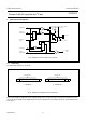

Table Of Contents
- 1 FEATURES
- 2 GENERAL DESCRIPTION
- 3 ORDERING INFORMATION
- 4 BLOCK DIAGRAM
- 5 PINNING
- 6 CHARACTERISTICS OF THE I 2 C-BUS
- 7 FUNCTIONAL DESCRIPTION
- 8 LIMITING VALUES
- 9 HANDLING
- 10 DC CHARACTERISTICS
- 11 I 2 C-BUS TIMING CHARACTERISTICS
- 12 PACKAGE OUTLINES
- 13 SOLDERING
- 14 DATA SHEET STATUS
- 15 DEFINITIONS
- 16 DISCLAIMERS
- 17 PURCHASE OF PHILIPS I 2 C COMPONENTS

2002 Nov 22 5
Philips Semiconductors Product specification
Remote 8-bit I/O expander for I
2
C-bus
PCF8574
5 PINNING
5.1 DIP16 and SO16 packages
SYMBOL PIN DESCRIPTION
A0 1 address input 0
A1 2 address input 1
A2 3 address input 2
P0 4 quasi-bidirectional I/O 0
P1 5 quasi-bidirectional I/O 1
P2 6 quasi-bidirectional I/O 2
P3 7 quasi-bidirectional I/O 3
V
SS
8 supply ground
P4 9 quasi-bidirectional I/O 4
P5 10 quasi-bidirectional I/O 5
P6 11 quasi-bidirectional I/O 6
P7 12 quasi-bidirectional I/O 7
INT 13 interrupt output (active LOW)
SCL 14 serial clock line
SDA 15 serial data line
V
DD
16 supply voltage
handbook, halfpage
1
2
3
4
5
6
7
8
16
15
14
13
12
11
10
9
INT
A0
A1
A2
P0
P1
P2
P3
SDA
V
SS
SCL
P7
P6
P5
P4
V
DD
PCF8574P
PCF8574AP
MBD979
Fig.2 Pin configuration (DIP16).
handbook, halfpage
1
2
3
4
5
6
7
8
16
15
14
13
12
11
10
9
INT
A0
A1
A2
P0
P1
P2
P3
SDA
V
SS
SCL
P7
P6
P5
P4
V
DD
PCF8574T
PCF8574AT
MCE001
Fig.3 Pin configuration (SO16).