
pca9539 datasheet
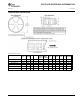


Table Of Contents
- 1 Features
- 2 Description
- Table of Contents
- 3 Revision History
- 4 Description (Continued)
- 5 Pin Configuration and Functions
- 6 Specifications
- 7 Parameter Measurement Information
- 8 Detailed Description
- 9 Application And Implementation
- 10 Power Supply Recommendations
- 11 Device and Documentation Support
- 12 Mechanical, Packaging, and Orderable Information

www.ti.com
PACKAGE OUTLINE
C
22X 0.65
2X
7.15
24X
0.30
0.19
TYP
6.6
6.2
1.2 MAX
0.15
0.05
0.25
GAGE PLANE
-80
B
NOTE 4
4.5
4.3
A
NOTE 3
7.9
7.7
0.75
0.50
(0.15) TYP
TSSOP - 1.2 mm max heightPW0024A
SMALL OUTLINE PACKAGE
4220208/A 02/2017
1
12
13
24
0.1 C A B
PIN 1 INDEX AREA
SEE DETAIL A
0.1 C
NOTES:
1. All linear dimensions are in millimeters. Any dimensions in parenthesis are for reference only. Dimensioning and tolerancing
per ASME Y14.5M.
2. This drawing is subject to change without notice.
3. This dimension does not include mold flash, protrusions, or gate burrs. Mold flash, protrusions, or gate burrs shall not
exceed 0.15 mm per side.
4. This dimension does not include interlead flash. Interlead flash shall not exceed 0.25 mm per side.
5. Reference JEDEC registration MO-153.
SEATING
PLANE
A 20
DETAIL A
TYPICAL
SCALE 2.000