
pca9539 datasheet
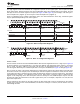


Table Of Contents
- 1 Features
- 2 Description
- Table of Contents
- 3 Revision History
- 4 Description (Continued)
- 5 Pin Configuration and Functions
- 6 Specifications
- 7 Parameter Measurement Information
- 8 Detailed Description
- 9 Application And Implementation
- 10 Power Supply Recommendations
- 11 Device and Documentation Support
- 12 Mechanical, Packaging, and Orderable Information

V
CC
3.3 V 5 V
LED
Pn
V
CC
V
CC
LED
Pn
100 kW
PCA9539
www.ti.com
SCPS130G –AUGUST 2005–REVISED JUNE 2014
Typical Application (continued)
9.1.1 Detailed Design Procedure
9.1.1.1 Minimizing I
CC
When I/O Is Used To Control Led
When an I/O is used to control an LED, normally it is connected to V
CC
through a resistor (see Figure 29).
Because the LED acts as a diode, when the LED is off, the I/O V
IN
is about 1.2 V less than V
CC
. The ΔI
CC
parameter in Electrical Characteristics shows how I
CC
increases as V
IN
becomes lower than V
CC
. For battery-
powered applications, it is essential that the voltage of I/O pins is greater than or equal to V
CC
, when the LED is
off, to minimize current consumption.
Figure 30 shows a high-value resistor in parallel with the LED. Figure 31 shows V
CC
less than the LED supply
voltage by at least 1.2 V. Both of these methods maintain the I/O V
CC
at or above V
CC
and prevent additional
supply-current consumption when the LED is off.
Figure 30. High-Value Resistor In Parallel With Led
Figure 31. Device Supplied By Lower Voltage
Copyright © 2005–2014, Texas Instruments Incorporated Submit Documentation Feedback 25
Product Folder Links: PCA9539