
pca9539 datasheet
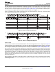


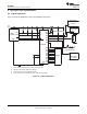


Table Of Contents
- 1 Features
- 2 Description
- Table of Contents
- 3 Revision History
- 4 Description (Continued)
- 5 Pin Configuration and Functions
- 6 Specifications
- 7 Parameter Measurement Information
- 8 Detailed Description
- 9 Application And Implementation
- 10 Power Supply Recommendations
- 11 Device and Documentation Support
- 12 Mechanical, Packaging, and Orderable Information

1 2
SCL
3 4 5 6 7 8
SDA
A A A
Data 0
Data to Register
R/W
9
00 0 0 0 0 1 1
MSB LSB Data1MSB LSB
A
Data to Register
S 1 1 1 0 1 A1 A0 0
1 2 3 4 5 6 7 8 9 1 2 3 4 5 6 7 8 9 1 2 3 4 5
P
Acknowledge
From Slave
Acknowledge
From Slave
Start Condition
Command ByteSlave Address
Acknowledge
From Slave
1 2
SCL
3 4 5 6 7 8
SDA
A A A
Data 0
R/W
t
pv
9
00 0 0 0 0 0 1
0.7 0.0
Data 11.7
1.0
A
S 1 1 1 0 1 A1 A0 0
t
pv
P
Slave Address
Command Byte Data to Port 0 Data to Port 1
Start Condition
Acknowledge
From Slave
Write to Port
Data Out from Port 1
Data Out from Port 0
Data Valid
Acknowledge
From Slave
Acknowledge
From Slave
PCA9539
www.ti.com
SCPS130G –AUGUST 2005–REVISED JUNE 2014
The eight registers within the PCA9539 are configured to operate as four register pairs. The four pairs are Input
Ports, Output Ports, Polarity Inversion ports, and Configuration ports. After sending data to one register, the next
data byte is sent to the other register in the pair (see Figure 24 and Figure 25). For example, if the first byte is
sent to Output Port 1 (register 3), the next byte is stored in Output Port 0 (register 2).
There is no limitation on the number of data bytes sent in one write transmission. In this way, each 8-bit register
may be updated independently of the other registers.
Figure 24. Write To Output Port Registers
Figure 25. Write To Configuration Registers
8.3.2.4.2 Reads
The bus master first must send the PCA9539 address with the least-significant bit set to a logic 0 (see Figure 22
for device address). The command byte is sent after the address and determines which register is accessed.
After a restart, the device address is sent again, but this time, the least-significant bit is set to a logic 1. Data
from the register defined by the command byte then is sent by the PCA9539 (see Figure 26 through Figure 28).
After a restart, the value of the register defined by the command byte matches the register being accessed when
the restart occurred. For example, if the command byte references Input Port 1 before the restart, and the restart
occurs when Input Port 0 is being read, the stored command byte changes to reference Input Port 0. The original
command byte is forgotten. If a subsequent restart occurs, Input Port 0 is read first. Data is clocked into the
register on the rising edge of the ACK clock pulse. After the first byte is read, additional bytes may be read, but
the data now reflect the information in the other register in the pair. For example, if Input Port 1 is read, the next
byte read is Input Port 0.
Data is clocked into the register on the rising edge of the ACK clock pulse. There is no limitation on the number
of data bytes received in one read transmission, but when the final byte is received, the bus master must not
acknowledge the data.
Copyright © 2005–2014, Texas Instruments Incorporated Submit Documentation Feedback 21
Product Folder Links: PCA9539