
pca9539 datasheet


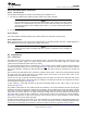

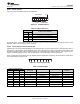

Table Of Contents
- 1 Features
- 2 Description
- Table of Contents
- 3 Revision History
- 4 Description (Continued)
- 5 Pin Configuration and Functions
- 6 Specifications
- 7 Parameter Measurement Information
- 8 Detailed Description
- 9 Application And Implementation
- 10 Power Supply Recommendations
- 11 Device and Documentation Support
- 12 Mechanical, Packaging, and Orderable Information

Data Output
by Transmitter
SCL From
Master
Start
Condition
S
1 2 8 9
Data Output
by Receiver
Clock Pulse for
Acknowledgment
NACK
ACK
SDA
SCL
Data Line
Stable;
Data Valid
Change
of Data
Allowed
SDA
SCL
Start Condition
S
Stop Condition
P
PCA9539
SCPS130G –AUGUST 2005–REVISED JUNE 2014
www.ti.com
Programming (continued)
Figure 19. Definition Of Start And Stop Conditions
Figure 20. Bit Transfer
Figure 21. Acknowledgment On I
2
C Bus
8.3.2 Register Map
Table 1. Interface Definition
BIT
BYTE
7 (MSB) 6 5 4 3 2 1 0 (LSB)
I
2
C slave address H H H L H A1 A0 R/W
P0x I/O data bus P07 P06 P05 P04 P03 P02 P01 P00
P1x I/O data bus P17 P16 P15 P14 P13 P12 P11 P10
18 Submit Documentation Feedback Copyright © 2005–2014, Texas Instruments Incorporated
Product Folder Links: PCA9539