
pca9539 datasheet


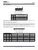

Table Of Contents
- 1 Features
- 2 Description
- Table of Contents
- 3 Revision History
- 4 Description (Continued)
- 5 Pin Configuration and Functions
- 6 Specifications
- 7 Parameter Measurement Information
- 8 Detailed Description
- 9 Application And Implementation
- 10 Power Supply Recommendations
- 11 Device and Documentation Support
- 12 Mechanical, Packaging, and Orderable Information

PCA9539
www.ti.com
SCPS130G –AUGUST 2005–REVISED JUNE 2014
Device Functional Modes (continued)
8.2.4.1 Interrupt Errata
The INT will be improperly de-asserted if the following two conditions occur:
1. The last I
2
C command byte (register pointer) written to the device was 00h.
NOTE
This generally means the last operation with the device was a Read of the input register.
However, the command byte may have been written with 00h without ever going on to
read the input register. After reading from the device, if no other command byte written, it
will remain 00h.
2. Any other slave device on the I
2
C bus acknowledges an address byte with the R/W bit set high
System Impact
Can cause improper interrupt handling as the Master will see the interrupt as being cleared.
System Workaround
Minor software change: User must change command byte to something besides 00h after a Read operation to
the PCA9539 device or before reading from another slave device.
NOTE
Software change will be compatible with other versions (competition and TI redesigns) of
this device.
8.3 Programming
8.3.1 I
2
C Interface
The bidirectional I
2
C bus consists of the serial clock (SCL) and serial data (SDA) lines. Both lines must be
connected to a positive supply via a pullup resistor when connected to the output stages of a device. Data
transfer may be initiated only when the bus is not busy.
I
2
C communication with this device is initiated by a master sending a Start condition, a high-to-low transition on
the SDA input/output while the SCL input is high (see Figure 19). After the Start condition, the device address
byte is sent, MSB first, including the data direction bit (R/W). This device does not respond to the general call
address.
After receiving the valid address byte, this device responds with an ACK, a low on the SDA input/output during
the high of the ACK-related clock pulse. The address inputs (A0 and A1) of the slave device must not be
changed between the Start and Stop conditions.
On the I
2
C bus, only one data bit is transferred during each clock pulse. The data on the SDA line must remain
stable during the high pulse of the clock period, as changes in the data line at this time are interpreted as control
commands (Start or Stop) (see Figure 20).
A Stop condition, a low-to-high transition on the SDA input/output while the SCL input is high, is sent by the
master (see Figure 19).
Any number of data bytes can be transferred from the transmitter to the receiver between the Start and the Stop
conditions. Each byte of eight bits is followed by one ACK bit. The transmitter must release the SDA line before
the receiver can send an ACK bit. The device that acknowledges must pull down the SDA line during the ACK
clock pulse so that the SDA line is stable low during the high pulse of the ACK-related clock period (see
Figure 21). When a slave receiver is addressed, it must generate an ACK after each byte is received. Similarly,
the master must generate an ACK after each byte that it receives from the slave transmitter. Setup and hold
times must be met to ensure proper operation.
A master receiver signals an end of data to the slave transmitter by not generating an acknowledge (NACK) after
the last byte has been clocked out of the slave. This is done by the master receiver by holding the SDA line high.
In this event, the transmitter must release the data line to enable the master to generate a Stop condition.
Copyright © 2005–2014, Texas Instruments Incorporated Submit Documentation Feedback 17
Product Folder Links: PCA9539