
pca9539 datasheet


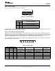

Table Of Contents
- 1 Features
- 2 Description
- Table of Contents
- 3 Revision History
- 4 Description (Continued)
- 5 Pin Configuration and Functions
- 6 Specifications
- 7 Parameter Measurement Information
- 8 Detailed Description
- 9 Application And Implementation
- 10 Power Supply Recommendations
- 11 Device and Documentation Support
- 12 Mechanical, Packaging, and Orderable Information

P0 A
0.7 × V
CC
0.3 × V
CC
SCL
P3
ÎÎÎ
ÎÎÎ
ÎÎÎ
ÎÎÎ
ÎÎÎ
t
pv
(see Note B)
Slave
ACK
Unstable
Data
Last Stable Bit
SDA
Pn
Pn
WRITE MODE (R/W = 0)
P0 A
0.7 × V
CC
0.3 × V
CC
SCL
P3
0.7 × V
CC
0.3 × V
CC
t
ps
t
ph
READ MODE (R/W = 1)
DUT
C
L
= 50 pF
(see Note A)
P-PORT LOAD CONFIGURATION
Pn
2 × V
CC
500 W
500 W
PCA9539
SCPS130G –AUGUST 2005–REVISED JUNE 2014
www.ti.com
Parameter Measurement Information (continued)
A. C
L
includes probe and jig capacitance.
B. t
pv
is measured from 0.7 × V
CC
on SCL to 50% I/O (Pn) output.
C. All inputs are supplied by generators having the following characteristics: PRR ≤ 10 MHz, Z
O
= 50 Ω, t
r
/t
f
≤ 30 ns.
D. The outputs are measured one at a time, with one transition per measurement.
E. All parameters and waveforms are not applicable to all devices.
Figure 15. P-Port Load Circuit And Voltage Waveforms
12 Submit Documentation Feedback Copyright © 2005–2014, Texas Instruments Incorporated
Product Folder Links: PCA9539