
pca9539 datasheet


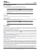

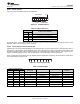

Table Of Contents
- 1 Features
- 2 Description
- Table of Contents
- 3 Revision History
- 4 Description (Continued)
- 5 Pin Configuration and Functions
- 6 Specifications
- 7 Parameter Measurement Information
- 8 Detailed Description
- 9 Application And Implementation
- 10 Power Supply Recommendations
- 11 Device and Documentation Support
- 12 Mechanical, Packaging, and Orderable Information

A
A
A
A
S 1 1 1 0 A11 A0 1
Data 1 1 PData 2
Start
Condition
8 Bits
(One Data Byte)
From Port
Data From PortSlave Address
R/W
87654321
t
ir
t
ir
t
sps
t
iv
Address Data 1 Data 2
INT
Data
Into
Port
B
B
A
A
Pn
INT
R/W A
t
ir
0.7 × V
CC
0.3 × V
CC
0.7 × V
CC
0.3 × V
CC
0.7 × V
CC
0.3 × V
CC
0.7 × V
CC
0.3 × V
CC
INT
SCL
View B−BView A−A
t
iv
R
L
= 4.7 kΩ
V
CC
C
L
= 100 pF
(see Note A)
INTERRUPT LOAD CONFIGURATION
DUT
INT
ACK
From Slave
ACK
From Slave
PCA9539
www.ti.com
SCPS130G –AUGUST 2005–REVISED JUNE 2014
Parameter Measurement Information (continued)
A. C
L
includes probe and jig capacitance.
B. All inputs are supplied by generators having the following characteristics: PRR ≤ 10 MHz, Z
O
= 50 Ω, t
r
/t
f
≤ 30 ns.
C. All parameters and waveforms are not applicable to all devices.
Figure 14. Interrupt Load Circuit And Voltage Waveforms
Copyright © 2005–2014, Texas Instruments Incorporated Submit Documentation Feedback 11
Product Folder Links: PCA9539