A.C. MODULAR GENERATOR SYSTEM OWNERS MANUAL MODEL#: LR-6.2 (60 Hz), LR-8 (60 Hz) and LR-6.
Smart Power® Systems A. C. MODULAR GENERATOR SYSTEM Page 1 of 49 Table of Contents Section Page Disclaimer .......................................................................................................................... 5 Description of Product...................................................................................................... 6 System Specifications ...................................................................................................... 9 Pre-Installation Guide .
Smart Power® Systems A. C. MODULAR GENERATOR SYSTEM Page 2 of 49 WARNING: Do not install or operate the A.C. modular generator system without reading this entire manual. The A.C. modular generator system will generate enough voltage to produce a fatal electrical shock. Do not perform any wiring installations or modifications while the system is operating. Never touch any live connections while the system is operating. Never operate the system with the generator wiring enclosure open.
Smart Power® Systems A. C. MODULAR GENERATOR SYSTEM Page 3 of 49 Never operate the system with leaks of any type. Clean up any hydraulic fluid that is spilled or has leaked out of the system. Hydraulic fluid is combustible, and ignition may occur. With the exception of oil filter periodic replacement, never modify or remove any of the components within the tray assembly. Never modify or remove any of the components within the pump. This includes all fittings that are originally provided with the A.C.
Smart Power® Systems A. C. MODULAR GENERATOR SYSTEM Page 4 of 49 Do not operate the system under electrical load with air in the hydraulic fluid (the system will make a growling sound). Do not allow anything to contact the hydraulic hoses that will cause a kink, pinch or chaffing. The A.C. modular hydraulic system generates hydraulic pressures approaching 3600 psi.
Smart Power® Systems A. C.
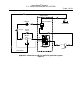
Smart Power® Systems A. C. MODULAR GENERATOR SYSTEM Page 6 of 49 Description of Product Hydraulic Generator Applications: This heavy-duty electronically controlled generator system has been designed to meet the most demanding mobile applications. The 60 Hz systems provide 120/240 volt AC @ 6200 or 8000 watts depending on model. The 50 Hz system provides 110/220 volt AC @ 6200 watts. How our System works: A generator driven by a hydraulic motor delivers the electrical power.
Smart Power® Systems A. C. MODULAR GENERATOR SYSTEM Page 7 of 49 BOOST BLOCK COOLER VENTURI BOOST x RESERVOIR y FILTER CHECK VALVE MOTOR BP REG IN PROPORTIONAL VALVE PUMP CASE DRAIN Hydraulic schematic for LR-6.
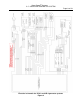
Smart Power® Systems A. C. MODULAR GENERATOR SYSTEM Page 8 of 49 Electrical schematic for LR-6.
Smart Power® Systems A. C. MODULAR GENERATOR SYSTEM Page 9 of 49 System Specifications MODEL OF GENERATOR Generator Type LR-6.2 (60 Hz) LR-8 (60 Hz) LR-6.2 (50 Hz) AC Inductive AC Inductive AC Inductive Speed Frequency Voltage 3600 RPM 60 Hz 240 VAC or 120/240 VAC 3600 RPM 60 Hz 240 VAC or 120/240 VAC 3000 RPM 50 Hz 220 VAC or 110/220 VAC Amperage 52A @ 120 VAC or 26A @ 240 VAC 66A @ 120 VAC or 33A @ 240 VAC 56A @ 110 VAC or 28A @ 220 VAC Output Power Hydraulic Motor 6.2 KW continuous 7.
Smart Power® Systems A. C. MODULAR GENERATOR SYSTEM Page 10 of 49 MODEL OF GENERATOR Fan LR-6.2, LR-8 12 Inch Pusher Voltage 12 Volts DC Amperage 22 Amps Filter 10 Micron Hydraulic Oil (recommended) (alternate) Dexron III ISO Approved Hydraulic Oil Maximum Viscosity Op. Temp. range (deg. F.) Hoses 4600 SUS (1000mm2/S) 60 SUS (10mm2/S) -13° F to 195° F JIC STD Pump Output 3600 psi, SAE All Others 1250 psi, SAE Fittings SAE Dry Weight (without pump) LR-6.
Smart Power® Systems A. C. MODULAR GENERATOR SYSTEM Page 11 of 49 Pre-Installation Guide Pre-Installation Check List WARNING: Never exceed 1500 RPM engine speed when the PTO is engaged. Doing so will void the system’s warranty. Do not approach a running A.C. modular generator when wearing long, loose items such as hair, jewelry, ties, clothing, etc. Direct contact with a rotating drive shaft can cause serious personal injury and/or damage to the system. 1.
Smart Power® Systems A. C. MODULAR GENERATOR SYSTEM Page 12 of 49 2. SPS models LR-6.2 and LR-8 can be mounted on top of a vehicle, in the open, without requiring any additional coverings. Reference Figure 3 and Figure 4 for the minimum clearances around the perimeter of the generator’s tray assembly. Also, do not position any obstructions directly in front of the system’s oil cooler.
Smart Power® Systems A. C. MODULAR GENERATOR SYSTEM Page 13 of 49 6" MINIMUM OBSTRUCTION FREE CLEARANCE 1" MAXIMUM SETBACK FROM FRONT OF COMPARTMENT Side view of LR-6.
Smart Power® Systems A. C. MODULAR GENERATOR SYSTEM Page 14 of 49 WARNING: Do not mount the tray assembly in any location that is not well ventilated. External heat sources elevating the hydraulic fluid and/or the generator temperature will result in premature wear and degraded system performance and void the system’s warranty. 3. The tray assembly must be mounted in a position that is higher than the pump.
Smart Power® Systems A. C. MODULAR GENERATOR SYSTEM Page 15 of 49 Installation Guide 1. Refer to the Chelsea PTO Installation Instructions (provided) to mount the PTO/pump unit on Ford Torqshift Transmission. 2. Locate and bore mounting holes for generator tray assembly as shown in Figure 6. Maintain minimum clearances as indicated in Figure 3 and Figure 4. Hole pattern for mounting LR-6.
Smart Power® Systems A. C. MODULAR GENERATOR SYSTEM Page 16 of 49 3. Mount the tray assembly as high as possible within the structure of the vehicle. The ideal location for the generator is at the top of the truck in the dunnage area. The manufacturer must also take sufficient precautions to ensure that the generator is not mounted in the path of the deck gun/water cannon. 4. Mount the hydraulic generator tray securely to vehicle.
Smart Power® Systems A. C. MODULAR GENERATOR SYSTEM Page 17 of 49 3.375 1.688 .208 CLEARANCE HOLE FOR #10 SCREW 4 PL. 2.000 1.688 3.375 Hole pattern for Command & Control Center Figure 8 6. Flush the hoses with fresh hydraulic fluid (Dexron III). Install hoses and tighten hose ends, using the Hose Installation Guidelines. See Figure 31 and for connection locations. WARNING: Lubricate hose fitting O-rings with clean hydraulic fluid (Dexron III) before installation to prevent damage to them.
Smart Power® Systems A. C. MODULAR GENERATOR SYSTEM Page 18 of 49 Never install a 90° fitting at the pump outlet or inlet. Never use an inlet line fitting less than 1”. Never install a hose tightly between connections. Leave length for the hoses to expand. Do not form loops in the hose that may collect air or cause kinking. Run hose as straight as possible (but not taut) between connections. To keep debris out of hoses while being positioned, cover the ends.
Smart Power® Systems A. C. MODULAR GENERATOR SYSTEM Page 19 of 49 for 50 Hz system only, the generator terminal strip should be configured as depicted below. This method ensures balanced loading of the generator, fully optimizing the system’s capabilities. Make the following wire connections at the terminal strip: a) place one jumper between wire 1 and wire 3. b) place the second jumper between wire 2 and wire 4. c) connect the phase wire from the breaker box to either wire 1 or wire 3.
Smart Power® Systems A. C. MODULAR GENERATOR SYSTEM Page 20 of 49 the system’s warranty. Replacement breakers must be obtained from Smart Power® Systems approved sources only. Do not perform any wiring installations or modifications while the system is operating. The A.C. modular generator system will generate enough voltage to produce a fatal shock. Never touch any live connections while the system is operating. Never operate the system with the generator cover removed. 8.
Smart Power® Systems A. C. MODULAR GENERATOR SYSTEM Page 21 of 49 The system controller has been designed to provide a purge option. With this option applied, the generator will turn at a reduced speed to minimize wear to the system’s hydraulic components while purging air from the system. Once enabled, the purge option will remain set until automatically reset by the system controller. The system controller will reset the option once the following two conditions are met: 1.
Smart Power® Systems A. C. MODULAR GENERATOR SYSTEM Page 22 of 49 Enabling System Purge Option The purge option can also be set by performing the following steps: Step 5: Press On/Off until y appears. Step 3: Hold Mode until Amps Line 1 Blinks 88. Release switch so 0Pt appears. Step 4: Press mode to make PvrG appear. Figure 10 1. If the Command & Control Center is dark, press the Mode switch to put the display into Normal mode. 2. If the Display looks like Figure 11, The purge option is enabled. 3.
Smart Power® Systems A. C. MODULAR GENERATOR SYSTEM Page 23 of 49 f. Check for hydraulic fluid leaks, all hose connections must be tight. Monitor the hydraulic fluid level, adding fluid as needed to keep the level in the sight gauge full. g. After 10 minutes, the system controller will automatically switch the generator to “0N”. Check to see that the generator is turning (The frequency display should indicate 0n). If it is not, press the On/Off switch on the Command & Control Center to start the generator.
Smart Power® Systems A. C. MODULAR GENERATOR SYSTEM Page 24 of 49 Step b: Hold Mode until Amps Line 1 Blinks 88. Release switch so 0Pt and AStr appear. Step c: Press On/Off until the desired value appears Figure 12 Enabling Auto-Start Option a. If the Command & Control Center is dark, press the Mode switch to put the Command & Control Center into Normal mode. b. Press and hold the Mode switch until the Amps Line 1 field begins blinking 88 (more than 10 seconds). Release the switch so 0Pt and AStr appear.
Smart Power® Systems A. C. MODULAR GENERATOR SYSTEM Page 25 of 49 Example of Command & Control Center in normal mode Figure 13 2. The PTO driving the SPS hydraulic pump must be engaged for the system to generate electricity. 3. The Command & Control Center is equipped with two Smart Touch switches, labeled “Mode” and “On/Off” respectively. These switches do not require pressure to be activated, but instead sense the presence or absence of your fingertip.
Smart Power® Systems A. C. MODULAR GENERATOR SYSTEM Page 26 of 49 4. If the system controller is powered on, but the generator is not running and no buttons are pressed for 5 minutes, the system will enter Quiescent mode. In Quiescent mode all displays are blank to conserve power. To return to Normal mode from Quiescent mode, press the Mode switch. 5.
Smart Power® Systems A. C. MODULAR GENERATOR SYSTEM Page 27 of 49 b. When the Command & Control Center is in Normal mode, pressing the Mode switch twice will cause the amount of time since the oil filter was last changed to be displayed (reference Figure 17): Time Since last Oil Filter Change in Hours. Example of oil filter run time display Figure 17 c.
Smart Power® Systems A. C. MODULAR GENERATOR SYSTEM Page 28 of 49 8. If the system measures a hydraulic oil temperature that exceeds 175°F (79°C), the system will begin displaying an alarm. If the system measures a hydraulic oil temperature that exceeds 180°F (82°C), the generator will automatically shut down in 30 minutes unless the shutdown is overridden.
Smart Power® Systems A. C. MODULAR GENERATOR SYSTEM Page 29 of 49 Step c: Press On/Off to answer “yes” and override the shutdown. Example of Command & Control Center in hot oil fault override confirmation Figure 20 c. If your answer was “yes” in the previous step, the confirmation screen shown in Figure 20 will be displayed. Again note the y and n labels below the Mode and On/Off switches. Press the On/Off switch to answer “yes” and override the shutdown.
Smart Power® Systems A. C. MODULAR GENERATOR SYSTEM Page 30 of 49 a. From the Normal mode display, press Mode, as if you wanted to display the oil temperature. The screen shown in Figure 21 will be displayed instead, asking if you want to “Run [with the] Oil Lo[w].” This screen will also be displayed if you attempt to start the generator with the condition present. b. Note the y and n labels below the Mode and On/Off switches.
Smart Power® Systems A. C. MODULAR GENERATOR SYSTEM Page 31 of 49 Step a: Press Mode to cause rvn and the y and n labels to appear. Step b: Press On/Off to answer “yes” and make the next screen appear. Example of Command & Control Center in temperature sensor fault override Figure 23 a. From the Normal mode display, press Mode, as if you wanted to display the oil temperature. The screen shown in Figure 23 will be displayed instead, asking if you want to “Run [with a] bad tsns [temperature sensor].
Smart Power® Systems A. C. MODULAR GENERATOR SYSTEM Page 32 of 49 Note: If you override the system and command it to operate with a faulty temperature sensor, the system may overheat and you will void the system’s warranty. 11. If the system determines the generator output voltage is out of range, it will begin displaying an alarm. This fault can be detected only when the generator is operating, and will automatically shut down the generator after 30 minutes unless the shutdown is overridden.
Smart Power® Systems A. C. MODULAR GENERATOR SYSTEM Page 33 of 49 Step c: Press On/Off to answer “yes” and override the shutdown. Example of Command & Control Center in voltage range fault override confirmation Figure 26 c. If your answer was “yes” in the previous step, the confirmation screen shown in Figure 26 will be displayed. Again note the y and n labels below the Mode and On/Off switches. Press the On/Off switch to answer “yes” and override the shutdown.
Smart Power® Systems A. C. MODULAR GENERATOR SYSTEM Page 34 of 49 Measured oil temperature in degrees fahrenheit Message advising the oil is cold (less than 40°F) Example of Command & Control Center when operating with cold hydraulic fluid Figure 27 Operating Modes when the system START button is activated (or when the system is in “autostart”): • When the meter displays hydraulic oil temperatures below 20°F, the hydraulic system will bypass the generator motor and the generator will not produce power.
Smart Power® Systems A. C. MODULAR GENERATOR SYSTEM Page 35 of 49 g. If the hydraulic fluid appears dirty or black in the reservoir sight gage, replace the fluid and filter immediately. Also, if the hydraulic fluid sustains a temperature over 175° F, replace the fluid immediately. Oxidation can occur naturally over time and can be accelerated with over temperature operation, affecting generator output. Always change the filter when the hydraulic fluid is changed.
Smart Power® Systems A. C. MODULAR GENERATOR SYSTEM Page 36 of 49 Press Mode until FLt and Xr are displayed Time Since last Oil Filter Change in Hours. Example of oil filter run time display Figure 28 4. The Command & Control Center will flash a fault when 250 hours have passed since the previous filter change.
Smart Power® Systems A. C. MODULAR GENERATOR SYSTEM Page 37 of 49 a. Press the Mode switch repeatedly until one of the screens shown in Figure 29 appears. b. While holding the Mode switch down, press and release the On/Off switch three times in succession, then release the Mode switch. The Oil Filter Fault display will be removed and replaced by another screen. The fault has been cleared and the timer reset. Note: Perform this step every time the filter is changed. c.
Smart Power® Systems A. C. MODULAR GENERATOR SYSTEM Page 38 of 49 Troubleshooting Guide Diagnostic: The Command & Control Center will display certain faults that can assist a service technician in trouble shooting a problem with the generator system. When these faults occur, the fault message will periodically flash on the Command & Control Center, interrupting the normal display. Reference Figure 30 for an example of an over-current fault.
Smart Power® Systems A. C. MODULAR GENERATOR SYSTEM Page 39 of 49 Diagnostic Faults: The following is a list of the diagnostic faults, with a brief explanation of each.
Smart Power® Systems A. C. MODULAR GENERATOR SYSTEM Page 40 of 49 Hydraulic Problems: 1. Cavitation: Cavitation is caused by trying to pump more fluid than is available at the pump inlet due to system restrictions. Pump cavitation sounds like “marbles” passing through the pump. Conditions frequently associated with cavitation are the following: a. Too many restrictive fittings such as elbows and reducers on the pump inlet hose. b. Tight bends or kinks in pump inlet hose and/or tubing. c.
Smart Power® Systems A. C. MODULAR GENERATOR SYSTEM Page 41 of 49 3. System Overheating: System overheating may be caused by re-circulation of hot air through oil cooler, dirty or obstructed oil cooler fins, restricted hydraulic fluid flow, excessive generator load, restricted airflow, previously overheated (old) fluid, non-functional fan, or improperly adjusted pump. a. b. c. d. e. Check the oil cooler fins for debris or damage. Clean and/or replace cooler.
Smart Power® Systems A. C. MODULAR GENERATOR SYSTEM Page 42 of 49 d. The stator field may be shorted or open. With a flashlight, check the generator windings visible through the ventilation slots. If the windings appear burnt in any area, the generator must be replaced. If the windings are not burnt, disconnect wires 1, 2, 3, and 4 from the terminal strip located in the generator wiring enclosure and make resistance measurement.
Smart Power® Systems A. C. MODULAR GENERATOR SYSTEM Page 43 of 49 h. The pump is faulty. If no faults are found in steps a. through g., the problem is likely to be a non-functional pump. Contact Smart Power® Systems at (231) 832-5525 for further instructions. 2. Output voltage exceeds 260 volts or falls below 220 volts AC on a 240 volt line for 60 Hz systems OR output voltage exceeds 240 volts or falls below 200 volts AC on a 220 volt line for 50 Hz system: a.
Smart Power® Systems A. C. MODULAR GENERATOR SYSTEM Page 44 of 49 SPS Model Matrix PARENT P/N DESCRIPTION COMMAND & CONTROL CENTER P/N TRAY ASM P/N PUMP ASM P/N RANGE STD=STANDARD RANGE WR=WIDE RANGE XWR=EXTENDED WIDE RANGE PUMP DISP. CC SHAFT K=KEYED S=SPLINED (STD) SHAFT ROTATION R=CW (STD), L=CCW MOTOR DISP. CC POWER OUTPUT KILOWATTS MANUAL P/N SPS MODEL MATRIX ER - LR SERIES 1700806 GENERATOR, LR-6, W/PTO PUMP, 2004-2010 1500047B 8570106 8510051 FIXED 23 S R 8 6.
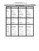
Smart Power® Systems A. C. MODULAR GENERATOR SYSTEM Page 45 of 49 Component Part Number Lists (Reference Figure 31 and Figure 32) ITEM NO. PARENT 1 2 GENEROIL ATOR COOLER 3 ASM, FAN 4 5 ASM, FILTER PR. SW., FAN CONT. 6 TRAY 7 8 9 FILTER HOUSING HYD. ELEMENT BOOST MOTOR 10 11 12 13 GAUGE, BREATHER ASM, FLUID OIL RES. PTO/PUMP PLUG LEVEL 14 15 ELEC. CONT. UNIT PROP. CONT.
Smart Power® Systems A. C. MODULAR GENERATOR SYSTEM Page 46 of 49 CONNECTOR: 12V POWER CONNECTOR: REMOTE ENABLE / BUZZER CONNECTOR: COMMAND AND CONTROL CENTER RESERVOIR DRAIN (3/8" HOSE) OIL FILTER ACCESS PANEL BOOST BLOCK OUTLET (1" HOSE TO PUMP INLET) VALVE INLET (5/8" HOSE FROM PUMP OUTLET) LR-6.
Smart Power® Systems A. C. MODULAR GENERATOR SYSTEM Page 47 of 49 15 5 1 12 9 10 8 3 14 6 THIS VIEW SHOWN WITH LID REMOVED 4 11 7 LID LATCH (2 EA) 2 LR-6.
Smart Power® Systems A. C. MODULAR GENERATOR SYSTEM Page 48 of 49 Manufacturers Limited Warranty Smart Power® Systems Hydraulic Generator Coverage period Provided such goods are operated and maintained in accordance with SPS’s written instructions, SPS warrants the hydraulic generators manufactured or supplied by it will be free from defects in material and workmanship for a period of five (5) years or one thousand (1,000) hours, whichever comes first, from the date of delivery to the first purchaser.
Smart Power® Systems A. C. MODULAR GENERATOR SYSTEM 5. Page 49 of 49 The cost of airfreight or other extraordinary expenses for shipment of parts over and above premium surface transportation. Limitation SPS is not responsible for the repair of generators that is required because of normal wear, accident, misuse, abuse, improper installation, corrosion, lack of maintenance, unauthorized modifications, the use of add-on or modified parts, improper storage or negligence.