
User's Manual
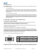
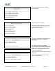
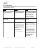
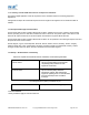
Table Of Contents

With a DCE adapter or a DTE when a “gender changer/null-modem” is connected, the (Female 9 pin D Type)
Pin-Outs are…
Pin Signal Pin Signal Pin Signal
1 N/C 4 DSR - N/C 7 CTS
2 TxD 5 Ground 8 RTS
3 RxD 6 DTR - N/C 9
A
uto-detect Pwr
The female connector is designed so that it can be plugged directly into a PC’s motherboard COM port.
If you are connecting it directly to a different device you may need an additional cable, such as a “cross-over” or “null-
modem” cable. Please refer to your device’s documentation for further details.
7. Connecting adapters over Bluetooth
There are 3 ways ADAPTER can be connected via Bluetooth.
a. Client/Server Pair: 2 ADAPTER’s, configured to perform a “true” cable replacement.
b. Server: Connecting TO ADAPTER from a remote Bluetooth device (Factory Default)
c. Client: ADAPTER is the Bluetooth device which initiates the connection
This section details all 3 methods.
7.1. Client/Server Pair: “Cable Replacement”
One of the strongest features of ADAPTER is that 2 of them can be configured to connect to each other and thus
behave almost exactly as a cable. This configuration is very straightforward, does not require any Bluetooth software
and is detailed below.
For ADAPTER’s to connect as a pair, one of the devices needs to be configured as a client device, and one as a server.
As the factory settings for ADAPTER are “Server” it follows then that only 1 of the ADAPTER pair needs any alternate
configuration from that supplied.
It is advisable that you first configure the communications settings (baud rate etc) for each ADAPTER so that they are
suitable for the devices into which you are plugging them. When configuring a pair of ADAPTER’s the Communications
parameters of each adapter do not have to match each other’s, only that of the devices into which they are connected.
Each ADAPTER has a unique Bluetooth Address (BD_ADDR). This is printed on a label on the base of every product,
but is also accessible from the “View Current Settings” menu detailed above.
For our example here, we will use an ADAPTER with a BD_ADDR of 000A-4F-00082D, which we’ll call the Server, and
a second, with a BD_ADDR of 000A-4F-0013BB, which we’ll call the Client. We’ll leave all other settings for this example as
factory defaults. As explained above we only need to change the settings of the Client device…
STBTIOBxXXPARSM User Guide 2.8 © Copyright SMART Modular Technologies 2004 Page 23 of 30