SMART HeightAdjustable Wall Mount (HAWM-UX/UF) Integration and Cabling Guide For SMART Board™ 600 and 800 interactive whiteboard projector systems
Product Registration If you register your SMART product, we’ll notify you of new features and software upgrades. Register online at www.smarttech.com/registration. Keep the following information available in case you need to contact SMART Technical Support.
Contents Product Registration B Contents i 1 Best practices for cabling your HAWM-UX/UF...................................................... 1 Introduction ..................................................................................................... 1 Best practices for cabling................................................................................ 2 Customizing your cables.................................................................................
ii | CO N T EN TS Placing cables for HAWM-UX/UF-mounted components ............................. 54 Placing cables for other components............................................................ 58 6 Cabling a 600i3 or D600i3 system to a HAWM-UX/UF ....................................... 65 Introduction ................................................................................................... 65 Mounting your HAWM-UX/UF mobility switch ..............................................
Chapter 1 Best practices for cabling your HAWM-UX/UF Introduction ..................................................................................................... 1 Best practices for cabling................................................................................ 1 Customizing your cables.................................................................................
2 | CH A P T E R 1 – B EST PRACTI CE S FOR C A B L I NG Y O U R H A W M - U X / U F Best practices for cabling Use the best practices in this section when placing cables for any type of interactive whiteboard system mounted on a HAWM-UX/UF. Following these best practices makes it easier to install peripheral devices to your interactive whiteboard system, improves the safety and security of your system and prevents damage to your devices.
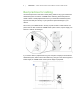
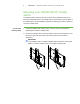
3 | CH A P T E R 1 – B EST PRACTI CE S FOR C A B L I NG Y O U R H A W M - U X / U F Mount your peripheral devices to a permanent location near the HAWM-UX/UF. If the peripheral device moves or can move, it can cause cable strain if the device is moved too far from and interferes with the HAWM-UX/UF.
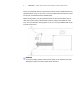
4 | CH A P T E R 1 – B EST PRACTI CE S FOR C A B L I NG Y O U R H A W M - U X / U F Customizing your cables Cables supplied by SMART for connecting your projector to the extended control panel (ECP) or interactive whiteboard are long enough to accommodate the additional distances your HAWM-UX/UF requires. You might need longer cables to attach your interactive whiteboard system to your computer and to other peripherals.
Chapter 2 Cabling an 885ix system to a HAWM-UX/UF Introduction ..................................................................................................... 5 Mounting your HAWM-UX/UF mobility switch ................................................ 6 Placing cables for HAWM-UX/UF-mounted components ............................... 7 Placing cables for other components............................................................
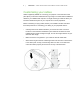
6 | CH A P T E R 2 – C A B L I N G A N 8 85 i x S Y S T E M T O A H A W M - U X /U F Mounting your HAWM-UX/UF mobility switch The mobility switch controls the vertical movement of the HAWM-UX/UF and your interactive whiteboard system. The mobility switch is wired directly to the rear panel of the HAWM-UX/UF. Use the installation guide with the following procedure to place and mount the mobility switch. To mount the mobility switch 1.
7 | CH A P T E R 2 – C A B L I N G A N 8 85 i x S Y S T E M T O A H A W M - U X /U F 3. Secure the mobility switch cable using a Phillips® No. 2 screwdriver and the two screws listed inside the HAWM-UX/UF installation guide. Secure the cable toward the side of the interactive whiteboard where you choose to mount the mobility switch and make sure that the cable is toward the bottom of the switch as you mount it. 4.
8 | CH A P T E R 2 – C A B L I N G A N 8 85 i x S Y S T E M T O A H A W M - U X /U F Using the SMART UX60 projector connection panel for HAWM-UX/UF-mounted components To access the projector connection panel and wire management clip, remove the input/output cover on the left side of the projector and remove the cable covers. For more information, see the SMART Board X800ix Interactive Whiteboard System Configuration and User’s Guide (smarttech.com/kb/150502).
9 | CH A P T E R 2 – C A B L I N G A N 8 85 i x S Y S T E M T O A H A W M - U X /U F Using the SMART UX60 projector ECP for HAWM-UX/ UF-mounted components The following diagram and list identify the ECP ports that connect to HAWM-UX/UF-mounted components.
10 | CH A P T E R 2 – C A B L I N G A N 8 85 i x S Y S T E M T O A H A W M - U X /U F Connecting the SMART UX60 projector’s ECP harness cable The ECP harness cable controls all signals and commands sent between the ECP and the projector. To install your ECP, follow the instructions in the SMART Board X885ix Interactive Whiteboard System Installation Instructions (smarttech.com/kb/ 149616). To connect your projector’s ECP harness cable 1.
11 | CH A P T E R 2 – C A B L I N G A N 8 85 i x S Y S T E M T O A H A W M - U X /U F Connecting the SMART UX60 projector to the wire management bundle (WMB) SMART recommends that when the WMB isn’t in use, you use the WMB’s magnetic connection to attach the WMB to the HAWM-UX/UF’s moving frame. By doing so, you prevent the WMB from shifting as the HAWM-UX/UF rises and descends.
12 | CH A P T E R 2 – C A B L I N G A N 8 85 i x S Y S T E M T O A H A W M - U X /U F 3. With the ECP mounted on the left, place the WMB around the back of the HAWM-UX/UF’s interactive whiteboard brackets, toward the left side of the interactive whiteboard for proximity to the ECP. 4. Place the WMB through the top cable clip you installed on the side of the HAWM-UX/UF. 5. Connect the WMB’s USB A plug to the ECP, and then loop the excess cable length into the cable clip. RCA connector pod ECP 6.
13 | CH A P T E R 2 – C A B L I N G A N 8 85 i x S Y S T E M T O A H A W M - U X /U F 1 Number To connect peripheral devices to your RCA connector pod 2 3 Function 1 RCA composite video input jack (for peripheral devices such as a DVD/Blu-ray player) 2 RCA audio jack (right input) 3 RCA audio jack (left input) 1. Place the device near the HAWM-UX/UF on a stable support and allow enough excess cable length to accommodate the HAWM-UX/UF’s rise and descent.
14 | CH A P T E R 2 – C A B L I N G A N 8 85 i x S Y S T E M T O A H A W M - U X /U F Connecting your SMART UX60 projector to the pen tray audio jack The audio and power jacks are located beside each other on the back of the pen tray. Audio jack To connect the projector to the audio jack Power jack 1. Connect the ends of the stereo Y cable to the VGA 1 and the VGA 2 inputs on your UF65 or UF65w projector. 2.
15 | CH A P T E R 2 – C A B L I N G A N 8 85 i x S Y S T E M T O A H A W M - U X /U F 2. Place the audio connection cable toward the right side of the HAWM-UX/UF, inserting the cable into the HAWM-UX/UF cable clips. Right speaker cable clip 3. Place the audio connection cable through the right speaker cable clip on the rear of the interactive whiteboard, toward the right speaker. 4.
16 | CH A P T E R 2 – C A B L I N G A N 8 85 i x S Y S T E M T O A H A W M - U X /U F Placing cables for other components Cables for peripheral devices connected to the projector but not mounted on the HAWM-UX/UF are at the greatest risk of damage, because they shift as the HAWM-UX/UF rises and descends.
17 | CH A P T E R 2 – C A B L I N G A N 8 85 i x S Y S T E M T O A H A W M - U X /U F Using the SMART UX60 projector connection panel for other components The following diagram and list identify the projector connection panel connections to components that don’t mount on the HAWM-UX/UF.
18 | CH A P T E R 2 – C A B L I N G A N 8 85 i x S Y S T E M T O A H A W M - U X /U F NOTES • SMART recommends that you use a VGA out connector on your source input, to simplify the cable placement. • The HDMI connector is intended for non-interactive audio-video content only, such as high-definition DVD/Blu-ray players. If you connect a cable from the HDMI port to a computer, your SMART Board interactive whiteboard doesn’t recognize touch commands.
19 To connect your projector power cable on the HAWM-UX/UF | CH A P T E R 2 – C A B L I N G A N 8 85 i x S Y S T E M T O A H A W M - U X /U F 1. Connect the power cable to the projector’s power socket. 2. Place the power cable through the foam-padded section of the cable clip, located under the projector, increase the length of cable between the projector and the clip by 1" (2.5 cm) and then close the clip. 3.
20 | CH A P T E R 2 – C A B L I N G A N 8 85 i x S Y S T E M T O A H A W M - U X /U F 5. When connecting cables from the projector to the interactive whiteboard, make sure that all cables pass between the two wall-mount interactive whiteboard brackets. Once the cables are through the brackets, place the ECP RCA connector pod harness cable toward the left side of the interactive whiteboard for proximity to the left-mounted ECP. 6. Attach the cables to the lower cable clips on the HAWM-UX/UF.
21 | CH A P T E R 2 – C A B L I N G A N 8 85 i x S Y S T E M T O A H A W M - U X /U F
Chapter 3 Cabling an 880i4 or 885i4 system to a HAWM-UX/UF Introduction ................................................................................................... 24 Mounting your HAWM-UX/UF mobility switch .............................................. 24 Placing cables for HAWM-UX/UF-mounted components ............................. 26 Placing cables for other components............................................................
22 | CH A P T E R 3 – C ABL IN G AN 8 80 i 4 O R 8 8 5 i 4 S Y S T E M T O A H A W M - U X / U F Mounting your HAWM-UX/UF mobility switch The mobility switch controls the vertical movement of the HAWM-UX/UF and your interactive whiteboard system. The mobility switch is wired directly to the rear panel of the HAWM-UX/UF. Use the installation guide with the following procedure to place and mount the mobility switch. To mount the mobility switch 1.
23 | CH A P T E R 3 – C ABL IN G AN 8 80 i 4 O R 8 8 5 i 4 S Y S T E M T O A H A W M - U X / U F 3. Secure the mobility switch cable toward the side of the interactive whiteboard where you choose to mount the mobility switch, using a Phillips No. 2 screwdriver and the two screws listed inside the HAWM-UX/UF installation guide,. Make sure that the cable is toward the bottom of the switch as you mount it. 4.
24 | CH A P T E R 3 – C ABL IN G AN 8 80 i 4 O R 8 8 5 i 4 S Y S T E M T O A H A W M - U X / U F Placing cables for HAWM-UX/UF-mounted components To prevent cable friction, SMART recommends that you first place the cables that don’t shift after they’re installed. Cables that connect components mounted to the HAWM-UX/UF don’t shift after they’re installed. To prevent cable friction, SMART recommends that you place these cables first.
25 | CH A P T E R 3 – C ABL IN G AN 8 80 i 4 O R 8 8 5 i 4 S Y S T E M T O A H A W M - U X / U F Using the SMART UF65 and SMART UF65w projector ECP for HAWM-UX/UF-mounted components The following diagram and list identify the ECP ports that connect to HAWM-UX/UF-mounted components.
26 | CH A P T E R 3 – C ABL IN G AN 8 80 i 4 O R 8 8 5 i 4 S Y S T E M T O A H A W M - U X / U F Connecting your SMART UF65 or SMART UF65w projector’s ECP harness cable The ECP harness cable controls all signals and commands sent between the ECP and the projector. Choose a side of the interactive whiteboard to install your ECP on, and then follow the instructions in theSMART Board X880i4 Interactive Whiteboard System Configuration and User’s Guide (smarttech.com/kb/150699).
27 | CH A P T E R 3 – C ABL IN G AN 8 80 i 4 O R 8 8 5 i 4 S Y S T E M T O A H A W M - U X / U F Connecting peripheral devices to the RCA connector pod The RCA connector pod enables you to connect DVD/Blu-ray players and other devices to our interactive whiteboard system using the three RCA jacks. The composite video connector and associated dual channel audio inputs on the RCA connector pod are for input only.
28 | CH A P T E R 3 – C ABL IN G AN 8 80 i 4 O R 8 8 5 i 4 S Y S T E M T O A H A W M - U X / U F Connecting your SMART UF65 and SMART UF65w projector to the pen tray audio jack The audio and power jacks are located beside each other on the back of the pen tray. Audio jack To connect the projector to the audio jack Power jack 1. Connect the ends of the stereo Y cable to the VGA 1 and the VGA 2 inputs on your UF65 or UF65w projector. 2.
29 | CH A P T E R 3 – C ABL IN G AN 8 80 i 4 O R 8 8 5 i 4 S Y S T E M T O A H A W M - U X / U F 4. Place the audio connection cable through the right speaker cable clip on the rear of the interactive whiteboard, toward the right speaker. Right speaker cable clip 5. Connect the dual channel audio output to the speaker’s connection panel, and bundle any excess cable in the right speaker cable clip. 6. Retrieve the speaker-to-speaker Molex (double-barreled) cable from the SBA-L packaging. 7.
30 | CH A P T E R 3 – C ABL IN G AN 8 80 i 4 O R 8 8 5 i 4 S Y S T E M T O A H A W M - U X / U F Placing cables for other components Cables for peripheral devices connected to the projector but not mounted on the HAWM-UX/UF are at the greatest risk of damage, because they shift as the HAWM-UX/UF rises and descends.
31 | CH A P T E R 3 – C ABL IN G AN 8 80 i 4 O R 8 8 5 i 4 S Y S T E M T O A H A W M - U X / U F Remove the input/output cover on the left side of the projector and remove the cable covers to access the projector connection panel and wire management clip . For more information, see the SMART Board X800i4 Interactive Whiteboard System Configuration and User’s Guide (smarttech.com/kb/150699).
32 | CH A P T E R 3 – C ABL IN G AN 8 80 i 4 O R 8 8 5 i 4 S Y S T E M T O A H A W M - U X / U F Using the SMART UF65 and SMART UF65w projector ECP for other components The following diagram and list identify the ECP connections to components that aren’t mounted to the HAWM-UX/UF.
33 To connect your projector power cable on the HAWM-UX/UF | CH A P T E R 3 – C ABL IN G AN 8 80 i 4 O R 8 8 5 i 4 S Y S T E M T O A H A W M - U X / U F 1. Pass the power cable through the boom and then connect it to the power socket. Make sure that the power cable is in the far right position in the cable slot. Cable slot 2.
34 | CH A P T E R 3 – C ABL IN G AN 8 80 i 4 O R 8 8 5 i 4 S Y S T E M T O A H A W M - U X / U F 6. Place the cables around the back of the HAWM-UX/UF toward the left side of the interactive whiteboard if the peripheral device or LAN connector is located on the left or toward the right side of the interactive whiteboard if the peripheral device or LAN connector is located on the right. 7. Attach the cables to the lower cable clips on the HAWM. 8.
35 | CH A P T E R 3 – C ABL IN G AN 8 80 i 4 O R 8 8 5 i 4 S Y S T E M T O A H A W M - U X / U F
Chapter 4 Cabling a 685ix or D685ix system to a HAWM-UX/UF Introduction ................................................................................................... 37 Mounting your HAWM-UX/UF mobility switch .............................................. 37 Placing cables for HAWM-UX/UF-mounted components ............................. 39 Placing cables for other components............................................................
36 | CH A P T E R 4 – C A B L I N G A 6 8 5 i x O R D 6 8 5 i x S Y S T E M T O A H A W M - U X / U F Mounting your HAWM-UX/UF mobility switch The mobility switch controls the vertical movement of the HAWM-UX/UF and your interactive whiteboard system. The mobility switch is wired directly to the rear panel of the HAWM-UX/UF. Use the installation guide with the following procedure to place and mount the mobility switch to your interactive whiteboard. To mount the mobility switch 1.
37 | CH A P T E R 4 – C A B L I N G A 6 8 5 i x O R D 6 8 5 i x S Y S T E M T O A H A W M - U X / U F 3. Secure the mobility switch cable using a Phillips No. 2 screwdriver and the two screws listed inside the HAWM-UX/UF installation guide. Secure the cable toward the side of the interactive whiteboard where you choose to mount the mobility switch and make sure that the cable is toward the bottom of the switch as you mount it. 4.
38 | CH A P T E R 4 – C A B L I N G A 6 8 5 i x O R D 6 8 5 i x S Y S T E M T O A H A W M - U X / U F Placing cables for HAWM-UX/UF-mounted components To prevent cable friction, SMART recommends that you first place the cables that don’t shift after they’re installed. Cables that connect components mounted to the HAWM-UX/UF don’t shift after they’re installed. The wire management bundle (WMB) shifts only if it’s connected to the wall or to a guest computer.
39 | CH A P T E R 4 – C A B L I N G A 6 8 5 i x O R D 6 8 5 i x S Y S T E M T O A H A W M - U X / U F Number Function 1 3.5 mm audio output connector (recommended for SBA-L speakers) 2 4-pin power mini-DIN 5V/2A connector (reserved for ECP harness cable) 3 7-pin mini-DIN connector (reserved for ECP harness cable) 4 3.
40 | CH A P T E R 4 – C A B L I N G A 6 8 5 i x O R D 6 8 5 i x S Y S T E M T O A H A W M - U X / U F Number Function 2 USB A jack (recommended location for interactive whiteboard USB cable) 3 DB15 ECP connector (reserved for ECP harness cable) Connecting your SMART UX60 projector’s ECP harness cable The ECP harness cable controls all signals and commands sent between the ECP and the projector.
41 | CH A P T E R 4 – C A B L I N G A 6 8 5 i x O R D 6 8 5 i x S Y S T E M T O A H A W M - U X / U F 3. Place the harness cable around the back of the HAWM-UX/UF’s interactive whiteboard brackets toward the left side of the interactive whiteboard if the ECP is mounted on the left or toward the right side of the interactive whiteboard if the ECP is mounted on the right. Upper cable clips 4. Place the harness cable through the upper cable clips on the side of the HAWM-UX/UF. 5.
42 | CH A P T E R 4 – C A B L I N G A 6 8 5 i x O R D 6 8 5 i x S Y S T E M T O A H A W M - U X / U F 2. Place the WMB through the cable management clip located under the projector. Make sure the WMB’s strain relief sits above the clip point. 3. If the ECP is mounted on the left, place the WMB around the back of the HAWM-UX/UF’s interactive whiteboard brackets, toward the left side of the interactive whiteboard.
43 | CH A P T E R 4 – C A B L I N G A 6 8 5 i x O R D 6 8 5 i x S Y S T E M T O A H A W M - U X / U F 5. Connect the WMB’s USB A plug to the ECP, and loop the excess cable length into the cable clip. 6. Use the WMB’s magnetic connection to attach the WMB to a metal surface, until you need to attach a guest computer to it.
44 | CH A P T E R 4 – C A B L I N G A 6 8 5 i x O R D 6 8 5 i x S Y S T E M T O A H A W M - U X / U F 2. Place the audio connection cable toward the right of the HAWM-UX/UF, inserting the cable into the HAWM-UX/UF cable clips. Right speaker cable clip 3. Place the audio connection cable through the right speaker cable clip on the rear of the interactive whiteboard, toward the right speaker. 4.
45 | CH A P T E R 4 – C A B L I N G A 6 8 5 i x O R D 6 8 5 i x S Y S T E M T O A H A W M - U X / U F Placing cables for other components Cables for peripheral devices connected to the projector but not mounted on the HAWM-UX/UF are at the greatest risk of damage, because they shift as the HAWM-UX/UF rises and descends.
46 | CH A P T E R 4 – C A B L I N G A 6 8 5 i x O R D 6 8 5 i x S Y S T E M T O A H A W M - U X / U F Using the SMART UX60 projector connection panel for other components The following diagram and list identify the projector connection panel connections to components that don’t mount to the HAWM-UX/UF.
47 | CH A P T E R 4 – C A B L I N G A 6 8 5 i x O R D 6 8 5 i x S Y S T E M T O A H A W M - U X / U F NOTES • SMART recommends that you use a VGA out connector on your source input to simplify the cable placement. • The HDMI connector is intended for non-interactive audio-video content only, such as high-definition DVD/Blu-ray players. If you connect a cable from the HDMI port to a computer, your SMART Board interactive whiteboard doesn’t recognize touch commands.
48 | CH A P T E R 4 – C A B L I N G A 6 8 5 i x O R D 6 8 5 i x S Y S T E M T O A H A W M - U X / U F Connecting the power, network and other peripheral device cables to your projector All cables that connect to your HAWM-UX/UF projector’s connection panel require a certain amount of slack to accommodate the projector’s rise and descent. When connecting your projector’s power cable, don’t bundle it with or place it parallel to other peripheral device cables you attach to your projector.
49 | CH A P T E R 4 – C A B L I N G A 6 8 5 i x O R D 6 8 5 i x S Y S T E M T O A H A W M - U X / U F 4. Place all cables through the foam-padded section of the cable clip located under the projector. Increase the length of cable between the projector and the clip by 1" (2.5 cm) and then close the clip. 5.
50 | CH A P T E R 4 – C A B L I N G A 6 8 5 i x O R D 6 8 5 i x S Y S T E M T O A H A W M - U X / U F Connecting composite video and USB devices to your projector’s ECP The ECP has three USB A jacks and one composite video RCA jack with associated dual-channel audio RCA jacks. SMART recommends that you install only small USB devices, such as a USB drive, or that you use a USB port on your computer for larger devices to eliminate the risk of cable damage.
Chapter 5 Cabling a 600i4 or D600i4 system to a HAWM-UX/UF Introduction ................................................................................................... 53 Mounting your HAWM-UX/UF mobility switch .............................................. 53 Placing cables for HAWM-UX/UF-mounted components ............................. 55 Placing cables for other components............................................................
52 | CH A P T E R 5 – C ABL IN G A 600 I4 OR D 600 I 4 S Y S T E M T O A H A W M - U X / U F Mounting your HAWM-UX/UF mobility switch The mobility switch controls the vertical movement of the HAWM-UX/UF and your interactive whiteboard system. The mobility switch is wired directly to the rear panel of the HAWM-UX/UF. Use the installation guide with the following procedure to place and mount the mobility switch. To mount the mobility switch 1.
53 | CH A P T E R 5 – C ABL IN G A 600 I4 OR D 600 I 4 S Y S T E M T O A H A W M - U X / U F 3. Secure the mobility switch cable toward the side of the interactive whiteboard where you choose to mount the mobility switch, using a Phillips No. 2 screwdriver and the two screws listed inside the HAWM-UX/UF installation guide. Make sure that the mobility switch cable is toward the bottom of the switch as you mount it. 4.
54 | CH A P T E R 5 – C ABL IN G A 600 I4 OR D 600 I 4 S Y S T E M T O A H A W M - U X / U F Placing cables for HAWM-UX/UF-mounted components To prevent cable friction, SMART recommends that you first place the cables that don’t shift after they’re installed. Cables that connect components mounted to the HAWM-UX/UF don’t shift after they’re installed. To prevent cable friction, SMART recommends that you place these cables first.
55 | CH A P T E R 5 – C ABL IN G A 600 I4 OR D 600 I 4 S Y S T E M T O A H A W M - U X / U F Using the SMART UF65 and SMART UF65w projector ECP for HAWM-UX/UF-mounted components The following diagram and list identify the ECP ports that connect to HAWM-UX/UF-mounted components.
56 To connect your projector’s ECP harness cables | CH A P T E R 5 – C ABL IN G A 600 I4 OR D 600 I 4 S Y S T E M T O A H A W M - U X / U F 1. Pass the ECP cable through the cable slot. NOTE The upper part of the ECP cable is too thick to fit inside the cable slot, so put the thinner part of the ECP cable in the cable slot. 2.
57 | CH A P T E R 5 – C ABL IN G A 600 I4 OR D 600 I 4 S Y S T E M T O A H A W M - U X / U F Connecting your SMART UF65 or SMART UF65w projector to the SBA-L projection audio system The HAWM-UX/UF is designed to accommodate mounting the SBA-L projection audio system directly to the interactive whiteboard. That way, when the speakers rise and descend with the HAWM-UX/UF’s and interactive whiteboard’s movement, there’s less risk of damage to the audio connection and power cables.
58 | CH A P T E R 5 – C ABL IN G A 600 I4 OR D 600 I 4 S Y S T E M T O A H A W M - U X / U F 7. Place the Molex cable through the left speaker cable clip, through the space between the HAWM-UX/UF and the interactive whiteboard. Left speaker cable clip 8. Place the cable through the right speaker cable clip. 9. Connect the Molex cable to both speakers, and bundle any excess cable in the left speaker cable clip.
59 | CH A P T E R 5 – C ABL IN G A 600 I4 OR D 600 I 4 S Y S T E M T O A H A W M - U X / U F Using the SMART UF65 and SMART UF65w projector connection panel for other components Remove the input/output cover on the left side of the projector and the cable covers to access the projector connection panel and wire management clip. For more information, see the SMART Board 600i4 and D600i4 Interactive Whiteboard System Configuration and User’s Guide (smarttech.com/kb/146184).
60 | CH A P T E R 5 – C ABL IN G A 600 I4 OR D 600 I 4 S Y S T E M T O A H A W M - U X / U F NOTE SMART recommends that you use a VGA out connector on your source input to simplify the cable placement. Using the SMART UF65 and SMART UF65w projector ECP for other components The following diagram and list identify the ECP connections to components that aren’t mounted to the HAWM-UX/UF.
61 | CH A P T E R 5 – C ABL IN G A 600 I4 OR D 600 I 4 S Y S T E M T O A H A W M - U X / U F Connecting the power, network and other peripheral device cables to your SMART UF65 or SMART UF65w projector Peripheral devices that don’t mount on the HAWM-UX/UF but that connect to your projector’s connection panel on the HAWM-UX/UF require a certain amount of slack in the cable for the projector’s rise and descent.
62 To connect your projector’s network and peripheral device cables on the HAWM-UX/UF | CH A P T E R 5 – C ABL IN G A 600 I4 OR D 600 I 4 S Y S T E M T O A H A W M - U X / U F 1. If you don’t want to connect a network cable, proceed to step 3. Otherwise, make sure you have a network cable with RJ45 plugs (not included) long enough to connect your projector to a LAN port. 2. Pass the network cable through the boom and connect the RJ45 plug on the network cable to the RJ45 port on the projector.
63 | CH A P T E R 5 – C ABL IN G A 600 I4 OR D 600 I 4 S Y S T E M T O A H A W M - U X / U F 11. If you don’t want to connect a network cable, proceed to the next step. Otherwise, connect the other end of the network cable to your LAN port. 12. Connect the other end of the cables to your peripheral devices. 13. Slowly test the movement of the unit, using the HAWM-UX/UF’s mobility switch. Make sure the cables aren’t taut at any range of the HAWM-UX/UF’s movement.
64 | CH A P T E R 5 – C ABL IN G A 600 I4 OR D 600 I 4 S Y S T E M T O A H A W M - U X / U F
Chapter 6 Cabling a 600i3 or D600i3 system to a HAWM-UX/UF Introduction ................................................................................................... 67 Mounting your HAWM-UX/UF mobility switch .............................................. 67 Placing cables for remotely mounted components .......................................
66 | CH A P T E R 6 – C ABL IN G A 600 I3 OR D 600 I 3 S Y S T E M T O A H A W M - U X / U F Mounting your HAWM-UX/UF mobility switch The mobility switch controls the vertical movement of the HAWM-UX/UF and your interactive whiteboard system. The mobility switch is wired directly to the rear panel of the HAWM-UX/UF. Use the installation guide with the following procedure to place and mount the mobility switch. To mount the mobility switch 1.
67 | CH A P T E R 6 – C ABL IN G A 600 I3 OR D 600 I 3 S Y S T E M T O A H A W M - U X / U F 3. Secure the mobility switch cable toward the side of the interactive whiteboard where you choose to mount the mobility switch, using a Phillips No. 2 screwdriver and the two screws listed in the HAWM-UX/UF installation guide. Make sure that the mobility switch cable is toward the bottom of the switch as you mount it. 4.
68 | CH A P T E R 6 – C ABL IN G A 600 I3 OR D 600 I 3 S Y S T E M T O A H A W M - U X / U F Placing cables for remotely mounted components Cables for peripheral devices connected to the projector but not mounted on the HAWM-UX/UF are at the greatest risk of damage, because they shift as the HAWM-UX/UF rises and descends.
69 | CH A P T E R 6 – C ABL IN G A 600 I3 OR D 600 I 3 S Y S T E M T O A H A W M - U X / U F 2. Draw a line on the wall behind the interactive whiteboard on the appropriate side, 36" (91.4 cm) from the floor, using a pencil and level. a. If you choose the left side, locate the lower left hand side of the interactive whiteboard and draw a line 1" (2.5 cm) from the left of the interactive whiteboard. This mark is for the top right screw’s drill hole on the ECP. b.
70 | CH A P T E R 6 – C ABL IN G A 600 I3 OR D 600 I 3 S Y S T E M T O A H A W M - U X / U F 7. Retrieve the four plastic anchors and four screws supplied for mounting the ECP, from the SMART UF55 or SMART UF55w projector packaging. Using a hammer, drive the plastic anchors into the wall at the four drill hole locations. 8. Attach but don’t tighten, two screws in the two top plastic anchors using a Phillips No. 2 screwdriver. Leave a 1/8" (3 mm) gap between the screw and the anchor. 9.
71 | CH A P T E R 6 – C ABL IN G A 600 I3 OR D 600 I 3 S Y S T E M T O A H A W M - U X / U F 10. Flip up the bottom panel of the ECP. Attach two screws in the two bottom plastic anchors using a Phillips No. 2 screwdriver. . Using the SMART UF55 and SMART UF55w projector’s connection panel for remotely mounted components To access the projector connection panel and wire management clip, first remove the input/output cover on the left side of the projector and remove the cable covers.
72 | CH A P T E R 6 – C ABL IN G A 600 I3 OR D 600 I 3 S Y S T E M T O A H A W M - U X / U F 1 2 Number 3 4 6 5 7 8 10 9 11 12 Function 1 RCA jack audio left/right input (reserved for ECP harness cable) 2 S-video input connector (reserved for ECP harness cable) 3 RCA jack audio left/right input (reserved for ECP harness cable) 4 RCA jack composite video input connector (reserved for ECP harness cable) 5 3.
73 | CH A P T E R 6 – C ABL IN G A 600 I3 OR D 600 I 3 S Y S T E M T O A H A W M - U X / U F NOTE SMART recommends that you use a VGA out from your source input to simplify the cable placement. Connecting your SMART UF55 and SMART UF55w projector¹s ECP harness cable The following diagram and list identify the ECP’s DB25 and VGA connections to the ECP harness cable.
74 To connect your projector power cable | CH A P T E R 6 – C ABL IN G A 600 I3 OR D 600 I 3 S Y S T E M T O A H A W M - U X / U F 1. Pass the power cable through the boom and then connect it to the power socket. Make sure that the power cable is in the far right position in the cable slot. Cable slot 2. Secure the power cable to the SMART UF55 or SMART UF55w projector’s wallmount bracket using a cable tie. Place the cable through the cable cutouts on the wall-mount bracket. 3.
75 | CH A P T E R 6 – C ABL IN G A 600 I3 OR D 600 I 3 S Y S T E M T O A H A W M - U X / U F 2. Pass the ECP cable through the cable slot. NOTE The upper part of the ECP cable is too thick to fit inside the cable slot, so put the thinner part of the ECP cable in the cable slot. 3.
76 | CH A P T E R 6 – C ABL IN G A 600 I3 OR D 600 I 3 S Y S T E M T O A H A W M - U X / U F 9. Attach a cable management clip (not included) to the cables or cable bundles, making sure there’s a minimum of 28" (71.1 cm) excess straight length or a 14" (35.6 cm) loose loop of cable. 10. If you don’t want to connect a network cable, proceed to the next step. Otherwise, connect the other end of the network cable to your LAN port. 11.
77 To connect your host computer’s audio and video output to the projector | CH A P T E R 6 – C ABL IN G A 600 I3 OR D 600 I 3 S Y S T E M T O A H A W M - U X / U F 1. Make sure you have VGA and 3.5 mm audio cables (not included) long enough to connect your computer to your SMART UF55 or SMART UF55w projector. 2. Pass the VGA and audio cables through the boom and connect your VGA cable to the Computer (VGA) 2 input on your projector. 3. Connect your 3.
78 To connect your host computer’s audio and video output to the ECP | CH A P T E R 6 – C ABL IN G A 600 I3 OR D 600 I 3 S Y S T E M T O A H A W M - U X / U F 1. Make sure you have a VGA and 3.5 mm audio cables (not included) long enough to connect your computer to your ECP. 2. Connect the VGA and 3.5 mm audio cables to the VGA and 3.5 mm input connector on the bottom of your ECP. 3.
79 | CH A P T E R 6 – C ABL IN G A 600 I3 OR D 600 I 3 S Y S T E M T O A H A W M - U X / U F Connecting peripheral devices to your SMART UF55 and SMART UF55w projectors’ ECP temporarily To connect a DVD/Blu-ray player, VCR, document camera, digital camera or other visual or audio-visual peripheral device, you must connect the device’s video and audio outputs to the ECP. You can have up to three peripheral devices and a host computer connected at one time.
80 | CH A P T E R 6 – C ABL IN G A 600 I3 OR D 600 I 3 S Y S T E M T O A H A W M - U X / U F Using the SMART UF55 and SMART UF55w projector connection panel for SBA and SBA-L projection audio systems The following diagram and list identify the SMART UF55 and SMART UF55w projectors’ connections to SBA and SBA-L speakers. To access the cable channel, remove the input/output cover on the left side of the projector and remove the cable covers.
81 | CH A P T E R 6 – C ABL IN G A 600 I3 OR D 600 I 3 S Y S T E M T O A H A W M - U X / U F 4. Place the audio connection cable through the right speaker cable clip on the rear of the interactive whiteboard, toward the right speaker. Right speaker cable clip 5. Connect the dual channel audio output to the speaker’s connection panel, and bundle any excess cable in the right speaker cable clip. 6. Retrieve the speaker-to-speaker Molex (double-barreled) cable from the SBA-L packaging. 7.
82 | CH A P T E R 6 – C ABL IN G A 600 I3 OR D 600 I 3 S Y S T E M T O A H A W M - U X / U F
Index Numerics 600i3 interactive whiteboard host computer to projector, 77 network cable connection, 74 SMART hub VE220 and SE240, 68 SMART UF55 projector power cable, 74 temporary connections, 79 600i4 interactive whiteboard, 51 mobility switch, 52 network cable, 62 peripheral cables, 62 SMART hub VE220 and SE240, 58 SMART UF65 projector power cable, 61 temporary connections, 63 685ix interactive whiteboard cabling, 35 ECP, 74 mobility switch, 36 network cable, 48 peripheral device, 48 SMART Hub VE220 and
84 | IN DE X E ECP 800i4 interactive whiteboard, 25 885ix interactive whiteboard, 9 SMART UF55 projector, 74 SMART UF55 projector remotemounted, 78 SMART UF65 projector, 25, 32, 60 SMART UX60 projector, 47 G movement switch 600i3 interactive whiteboard, 66 600i4 interactive whiteboard, 52 685ix interactive whiteboard, 36 800i4 interactive whiteboard, 22 885ix interactive whiteboard, 6 P path of travel, 2 power outlets best practice for cabling, 2 guest computer cable placement, 2 H Height-Adjustable
85 | IN DE X 25, 55 ECP for other components, 32 for HAWM-mounted components, 24 for other components, 31, 59 HAWM-mounted components, 54 power cable, 61 SBA-L audio system, 28, 57 SMART UX60 projector 685ix interactive whiteboard, 43 ECP diagram for HAWM-mounted components, 39 ECP for HAWM-mounted, 9 ECP for HAWM-mounted components, 47 ECP for other components, 18, 47 for HAWM-mounted components, 8 for other components, 17 HAWM-mounted components, 38 other mounted components, 46 power cable, 19, 48 SBA-
86 .
Toll Free 1.866.518.6791 (U.S./Canada) or +1.403.228.5940 www.smarttech.