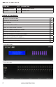
HDR8X8 HDR16X16 8/16-port HDMI Matrix Switch with Front Panel, RS-232, IR, and TCP/IP Control COMPLIANT Installation Manual Made in the U.S.A. www.smartavi.com www.smartavi.
What’s in the Box? PART NO.
Introduction The HDR8X8/HDR16X16 conforms to the HDMI (High Definition Media Interface) standard with HDCP compliance and provides a connection to view any eight/sixteen HDMI video sources on any combination of eight/sixteen video displays. The matrix configuration provides maximum flexibility, allowing switching between any high-definition source and/or display. The HDR8X8/HDR16X16 provides HDMI output up to 40 feet and at HDTV resolutions of 480p, 720p, 1080i and 1080p.
Technical Specifications VIDEO HDTV Resolutions TV Resolution Input Interface Output Interface Input Cable Length Output Cable Length 480p, 720p, 1080i, 1080p, Supports all DVI-D Resolutions 480i (8/16) HDMI Type A 19-pin Female TMDS (8/16) HDMI Type A 19-pin Female TMDS Up to 40 ft. Up to 40 ft. OTHER Warranty Control Power Dimensions Weight HDR 16X16 Approvals Power Supply Approvals Limited 1 Year Parts and Labor Panel, RS-232, IR, USB and TCP/IP Internal 100-240 VAC 19”W x 5.25”H (2U) x 7”D 10 lbs.
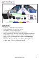
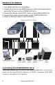
Application Diagram 40 ft. over HDMI 40 ft.
Hardware Installation 1. Turn off all input devices and displays. 2. Connect the male to male HDMI extension cables to the input devices and to the “IN” ports on the HDR8X8/HDR16X16. 3. Connect the displays to the “OUT” ports on the HDR8X8/HDR16X16. 4. Connect the power cord and power-on the HDR8X8/HDR16X16. 5. Power on the input devices and the displays.
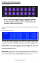
Using the Front Panel Control Front Panel Buttons NOTE: To lock the front panel buttons to avoid any accidental changes, press ESC + MENU + ENTER + SWITCH at the same time. The display will indicate that it is locked. Repeat the procedure to unlock the front panel. During normal operation, you will see a list of ports on the front panel display. Default Display HDR16X16 To assign an output to an input, press SWITCH. A blinking block cursor will appear.
Main Menu To view the menu, press MENU. There are 6 menu options available: RS-232 Acknowledge - Sets the HDR8X8/HDR16X16 to send a confirmation that an RS-232 command has been received. RS-232 Checksum - Sets the HDR8X8/HDR16X16 to verify all RS-232 data for errors in transmission. Send Update - Sets the HDR8X8/HDR16X16 to send an RS-232 command back to the controller when the configuration is changed via the front panel or remote control (optional).
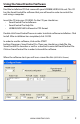
Using the SmartControl Software Find the Installation CD that came with your HDR8X8/HDR16X16 unit. This CD has the SmartControlPro software that you will need in order to control the unit using a computer. Insert the CD into your CD-ROM. On the CD you should see: • SmartControl Pro Installer.exe • SmartControl Pro Help File • HDR8X8/HDR16X16 Manual in PDF format Double click SmartControlPro.exe in order to initiate software installation. Click Install. After installation has completed, click CLOSE.
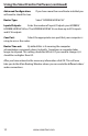
Using the SmartControl Software (continued) Advanced Configuration: will want to check this box. If you have more than one Router installed you Router Type: Select “HDR8X8/HDR16X16” Inputs/Outputs: Enter the number of Inputs/Outputs your HDR8X8/ HDR8X8/HDR16X16 has. The HDR8X8/HDR16X16 can have up to 8/16 inputs and 8/16 outputs. Com Port: Select the appropriate com port that your computer is using to access the router.
Using the SmartControl Software (continued) Main Routing Window On this screen you will notice the input buttons running down the left side while the output buttons run across the top. They are each labeled 1 through 8/16. Note: The three small colored buttons at the lower right labeled ALL, VIDEO, and AUDIO are not available if AV Split was not checked when you configured your router. www.smartavi.
Using the SmartControl Software (continued) The Main Routing Window enables you to control the router(s) connections by means of the Crosspoint panel, the button panel, or with pre-recorded routes called macros. Crosspoint Panel: This is probably the simplest way to route the connections. Simply click on the cross point itself. The input on the left will then be routed to the output above. Note: Inputs can be routed to several different outputs, but each output can only have a single input at any one time.
Using the SmartControl Software (continued) The Button Panel: These are the numbered buttons across the top and left sides. Click an output button on the top, and then click an input button on the left. Options for using the Button Panel • Output Options: To select multiple outputs next to each other, click on one output, then hold the shift key down and click the last output. When the input is clicked, it is routed to all selected outputs.
Using the SmartControl Software (continued) Macros: This section of the window is used to save and play back macros. Macros store a set sequence of routes. To record a macro: 1. Click on the Record button (last button shown). A blinking “recording” message below this button will be displayed to indicate that all routes are being recorded. 2. Select the desired crosspoints. There is no limit on the number of routes you may record. 3.
Optional Control Methods IR: Many system professionals prefer the IR control interface because it offers greater flexibility to manage the HDR8X8/HDR16X16 at a distance. In some cases, the displays will not be visible from the matrix. In these situations it is necessary to control the matrix with Infrared control. RS-232: Controlling the HDR8X8/HDR16X16 has never been simpler with SmartControl software.
Using the IR Remote Control (optional) You have the option of controlling the HDR8X8/HDR16X16 via Remote Control. The remote is used to control the HDR8X8/HDR16X16. The SM-EYE must be connected to the HDR8X8/HDR16X16 ( this is an optional connector not always available in all boxes) in order to interface the remote control with the matrix.
Using RS-232 Control (optional) How to properly create an RS-232 connection between a PC and most SmartAVI RS-232 compliant devices Establish a connection to your RS232 compliant device: 1. 2. 3. Connect a straight through male to female RS-232 cable (shown on right) to the RS-232 connector on the PC. Connect the other end of the cable to the RS-232 compliant device. Power on the device. Male to Female Straight Cable (not provided) Setting up the Terminal application: 1. 2. 3. 4.
Using RS-232 Control (continued) There are two primary modes of operation for the HDR8X8/HDR16X16: Command Mode and Debug Mode. When connecting to the HDR8X8/HDR16X16 via RS-232, it will start in Command Mode (see Command Mode p. 19 for options). Debug Mode is a more userfriendly way of operating the HDR8X8/HDR16X16 and includes instructional menus. The following section details the use of the Debug Mode.
Using RS-232 Control (continued) To display the help menu for a list of commands, type “? ” DBG>? =========================================================================== Command Line Interface Help: d Enable/Disable debug d [on][off] sw Switch Port sw [output] 1-16 [input] 1-16 br Broadcast Port br [input] 1-16 om Set output mode om [output] [mode# (0-2) | ?] o Enable/Disable Output o [output] [0 = disable | 1 = enable q Query Crosspoints h Toggle Hotplug h [input] reset Restore Factory Settings
Using RS-232 Control (continued) Command Mode: Command Mode allows raw commands to be sent to the HDR8X8/ HDR16X16 to control its various functions without the use of a menu or prompt. This mode is intended for advanced use only. There are two types of commands that you can issue the HDR8X8/HDR16X16: Commands with CHECKSUM and Commands without CHECKSUM. The CHECKSUM is a method of error correction that ensures the command has been properly transmitted to the HDR8X8/HDR16X16.
Using RS-232 Control (continued) Command Mode continued: 5) To query crosspoints from PC: //FxxU • If all outputs are connected to input 1 then a 4x4 Matrix will respond with <0x80><0x80><0x80><0x80> • The router will send back one byte for each output and the string ends with a . The first byte sent is Output #1. In the example above, since there are 5 bytes total, we know that there are 4 outputs.
Using RS-232 Control (continued) Command Mode continued: Sending Commands WITHOUT CHECKSUM 1) To set a video crosspoint: \\FxxMyyIzz e.g.
Using the SMTCP module (optional) The SMTCP-2 is an RS-232 control module that allows most SmartAVI switching matrixes to be controlled remotely via HTTP or TELNET. Manage the switching functions of your matrix with ease from anywhere in the world. With the SMTCP-2 you can save up to 10 preset input/output configurations for easy access. TELNET access provides transparent command control of your matrix, perfect for use with automated thirdparty control software.
Using the SMTCP module (continued) Connecting to the SMTCP-2 for the first time The first time you connect the SMTCP-2, you will need to perform the following steps to set the initial configuration. This includes establishing an HTTP connection and manually setting the IP address for the SMTCP-2. 1. Power off all devices. 2. Use a female to male Straight-Through RS-232 (Serial) cable to connect the SMTCP-2 to the computer. 3.
Using the SMTCP module (continued) 8. Open a web browser and navigate to the IP address that is indicated. You will be prompted to enter a username and password. 9. The default login (case sensitive) is as follows: User ID: Admin Password: Pass 10. Once connected to the SMTCP-2, you will see the following menu of options: 1. Matrix 2. Frame Address 3. Device Config 4. Network Setting 5.
Using the SMTCP module (continued) Controlling the SMTCP-2 via HTTP Once you have completed the Initial Setup for the SMTCP-2, you can now begin configuring it for your matrix. The following details the individual menu options in the web interface: Matrix Menu The matrix menu allows you to set the crosspoints for the matrix. Crosspoints are used to route signals from the individual inputs to individual outputs. The output channels can only have one input, but each input can have several outputs.
Using the SMTCP module (continued) Device Config Menu The device configuration menu allows you to select the type of matrix you are using, specify the dimensions of the matrix, and assign names to the inputs, outputs and presets, reset the names and reset the system to factory defaults. To begin, set the type of device you are using from the drop-down menu labeled Device Type and specify the Matrix Dimensions. After specifying the Matrix Dimensions, press the Submit button to make the changes.
Using the SMTCP module (continued) User Administration Menu The User Administration menu allows you to change the user name and password for the SMTCP-2. The default user name for the SMTCP-2 is Admin and the password is Pass. Once you modify the login information, press the Submit button to make the changes. Controlling the SMTCP-2 via TELNET Commands may be sent transparently to the matrix via a TELNET connection to the SMTCP-2.
Using the SMTCP module (continued) Connecting to the SMTCP-2 for the first time WITHOUT DHCP The first time you connect the SMTCP-2, you will need to perform the following steps to set the initial configuration. This includes establishing an HTTP connection and manually setting the IP address for the SMTCP-2. 1. Power off all devices. 2. Use a female to male Straight-Through RS-232 (Serial) cable to connect the SMTCP-2 to the computer. 3.
Limited Warranty Statement A. Extent of limited warranty 1. SmartAVI Technologies, Inc. warrants to the end-user customers that the SmartAVI product specified above will be free from defects in materials and workmanship for the duration of 1 year, which duration begins on the date of purchase by the customer. Customer is responsible for maintaining proof of date of purchase. 2.
© Copyright 2012 SmartAVI, All Rights Reserved NOTICE The information contained in this document is subject to change without notice. SmartAVI makes no warranty of any kind with regard to this material, including but not limited to, implied warranties of merchantability and fitness for any particular purpose. SmartAVI will not be liable for errors contained herein or for incidental or consequential damages in connection with the furnishing, performance or use of this material.
At SmartAVI, we offer a complete line of audio video solutions for high-quality signal switching and distribution. Our devices support multiple signal types including VGA, DVI, HDMI, USB, RS232, IR and more. HDMI SOLUTIONS HDMI EXTENDERS At SmartAVI, we offer a complete line of HDMI solutions for high-quality HDMI signal switching and distribution. Our HDMI devices support all of your HDTV’s, DVR’s, DVD Players, Blue-ray players, video game consoles, computers and many other HDMI compliant devices.