
Installation Guide


INSTALLATION NOTES
• TS4-F, TS4-R-F, and TS4-A-F are shipped in the OFF position and will
measure 0.6V at the output when the keep-alive signal is not
present.
• Failing to follow the sequence of installation steps may result in TS4
damage not covered under warranty.
• Connect all TS4-R-F or TS4-A-F units to their respective modules
before connecting their outputs in series.
• Install all TS4-F, TS4-R-F, or TS4-A-F units before powering on the RSS
Transmitter.
• Never apply an external voltage source to a module or string
equipped with TS4-F, TS4-R-F, or TS4-A-F units.
• If parallel string connections are needed, rst connect the TS4-F, TS4-R-F,
or TS4-A-F to the PV modules, then connect all TS4-F, TS4-R-F, or TS4-A-F
outputs in series, and nally pass one side (+ or -) of the homeruns
through the PLC transmitter to turn the system ON.
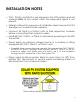
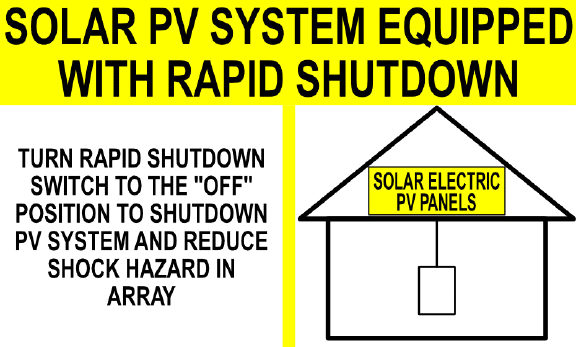
• Place rapid shutdown system label no more than 1m (3ft) from
initiator (AC disconnect) or service panel containing means of
disconnection if not at same location.
9
Place safety labels in proper location