
Installation Manual


12. Connect the conductors to the connecting
terminal plate in accordance with the labeling.
Insert each conductor into the corresponding
round terminal up to the stop. Always connect
the positive terminal and the negative terminal of
a string to the same input, and keep in mind that
the round terminals C+ and C- of inverters with
two DC inputs must not be assigned.
DC-in
1
A+ B+ C+ A− B C− −
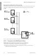
13.
Risk of fire due to connecting the conductors to the clamping contacts
By connecting the conductors to the clamping contacts a fire can occur.
• Make sure that the conductors are
connected to the round terminals and not
to the square clamping contacts.
DC-in
1
A+ B+ C+ A− B C− −
DC-in
1
A+ B+ C+ A− B C− −
14. Ensure that the correct conductors are assigned to the round terminals.
15. Ensure that the conductors are plugged completely into the round terminals up to the
insulation.
6.5 Connecting the Multifunction Relay
6.5.1 Procedure for connecting the multifunction relay
Procedure See
1. Select for which operating mode you would like to use the
multifunction relay.
see section6.5.2, page37
2. Connect to the multifunction relay according to the operat-
ing mode and the associated connection variant.
see section6.5.3, page37
and see section6.5.4,
page40
3. After commissioning the inverter, change the operating
mode of the multifunction relay, if necessary.
User manual under
www.SMA-Solar.com
6 Electrical Connection
SMA Solar Technology America LLC
Installation ManualSB30-77-1SP-US-40-IA-xx-1336
ENGLISH