
Installation Manual


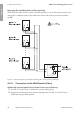

Figure 10 : Connection overview for parallel connection of the DC inputs A and B
Requirements for the PV modules per input:
☐ All PV modules must be of the same type.
☐ All PV modules must be aligned and tilted identically.
☐ If inputs A and B are connected in parallel, the PV modules of inputs A and B must be
identically aligned and the same number of PV modules connected in series must be
connected to all strings of inputs A and B.
☐ The maximum inverter system voltages permitted may not be exceeded (see Section10
"Technical Data", page60).
☐ The maximum short-circuit current may not be exceeded (see Section10 "Technical Data",
page60).
Additionally required material (not included in the scope of delivery):
☐ Conduits: 21mm (0.75in) or smaller with a proper reducing bush
☐ Rain-tight conduit fittings for wet locations complying with UL 514B: 21mm (0.75in) or
smaller with a proper reducing bush
Requirements for the DC conductors:
☐ The DC connecting terminal plate temperature rating is +90°C (+194°F).
☐ The conductors with regards to its ampacity, rated temperatures, operating conditions and its
power loss must be made in accordance with the local standards and the National Electrical
Code
®
ANSI/NFPA 70 or the Canadian Electrical Code
®
CSA C22.1.
☐ Conductor type: copper wire
☐ Maximum permissible temperature: +75°C (+167°F) or +90°C (+194°F)
☐ The conductors must be made of solid wire, stranded wire or fine stranded wire. When using
fine stranded wire, bootlace ferrules must be used.
☐ Conductor cross-section: 2.5mm² to 10mm² (14AWG to 8AWG)
6 Electrical Connection
SMA Solar Technology America LLC
Installation Manual 33SB30-77-1SP-US-40-IA-xx-13
ENGLISH