
User Manual

SMA Solar Technology America LLC 3 Multi-tap Connector use with SMA Rapid Shutdown System and
Technical Information RSS-Compability-US-TI-en-10 3
3 Multi-tap Connector use with SMA Rapid Shutdown System and
SBx.x-1SP-US-40 Inverters
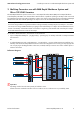
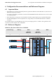
The SMA Rapid Shutdown System consists of one or more Rapid Shutdown Boxes (RSB) and one Rapid Shutdown
Controller (RSC). The RSB is a two channel device. Each channel is capable of operating at 20 Amps of PV current and
has a Maximum Circuit Current rating of 36 Amps. In many cases, three or more strings may be connected to each Rapid
Shutdown Box with each channel operating at 16 Amps or more. See the installation manual for more details.
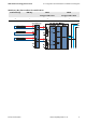
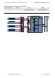
For the SBx.x-1SP-US-40 inverters, each inverter can be wired with
• Up to 3 independent MPP inputs – (A), (B), and (C) – operating at up to 10 Amps and rated at 18 Amps Maximum
Circuit Current
or
• 2 combined MPP inputs and a single MPP input – (A||B) and (C) – inputs A and B operating in parallel at up to
20 Amps and rated at 36 Amps Maximum Circuit Current. This configuration has two strings on input (A||B) and
one on input (C) per the diagram below. Three wire, insulated, multi-tap connectors are used to combine inputs A
and B on the inverter.
Reference Diagram
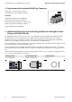
For example
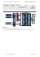
For a three string installation of typical PV modules with approximately 8.5 Amps Imp and 9.5 Amps Isc, an installer
can connect two strings to RSB Channel A input giving a total combined Imp of 17 Amps and a total Maximum Circuit
Current of 23.8 Amps. Channel B would be connected to a single string of PV modules with a total Imp of 8.5 Amps
and a total Maximum Circuit Current of 10.6 Amps.
Important
A/B Strings need to have the same quantity of modules in series.
3-Wire Connectors needed to transition from one conductor to two conductors are not provided by SMA.