
Installation Guide
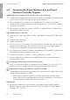
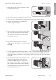

Connecting the conductors to the Rapid Shutdown Controller
+ A −
− B +
RSC
NC 1
2
X 1
2
X
X 1
2
X
NC 1
2
X 1
2
X
X 1
2
X
1
2
3
4
5
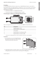
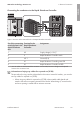
Figure 9: Overview of the terminal blocks in the Rapid Shutdown Controller
Pin of the connecting
terminal plate in the
Rapid Shutdown
Box
Terminal in the
Rapid Shutdown
Controller
Assignment
1 X2 Supply voltage (+12V)*
2 2 Rapid Shutdown Controller switch
3 NC 1 Ground (0V)
4 X1 Rapid Shutdown Controller green LED
5 X1 Rapid Shutdown Controller red LED
* You can select on which terminal the connection is to be made, because a bridge must be placed
between the connections later.
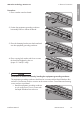
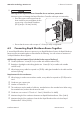
Information on laying tray cables for exposed run (TC-ER)
The procedure for using conduits is described in this section. Instead of conduits, you can also
use tray cables for exposed run (TC-ER).
• When using tray cables for exposed run (TC-ER), select suitable cable glands and
attach to the enclosure opening instead of the conduit. When doing so, ensure that the
enclosure opening is sealed and no moisture can enter.
6 Electrical Connection
SMA Solar Technology America LLC
Installation Manual 25RSS-US-IA-xx-13
ENGLISH