
Installation Guide

Procedure:
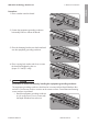
If several Rapid Shutdown Boxes are present in your Rapid Shutdown System, connect the first
Rapid Shutdown Box to the Rapid Shutdown Controller first. To do so, first connect one end of the
conductors to the Rapid Shutdown Box and then connect the other end of the conductors to the
Rapid Shutdown Controller.
• Connect the conductors to the Rapid Shutdown Box.
• Connect the conductors to the Rapid Shutdown Controller.
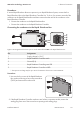
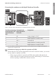
Connecting the conductors to the Rapid Shutdown Box
Figure 8: Pin assignment of the lower pin row on the terminal block RSC in the Rapid Shutdown Box
Pin Assignment
1 Supply voltage (+12V)*
2 Rapid Shutdown Controller switch
3 Ground (0V)
4 Rapid Shutdown Controller green LED
5 Rapid Shutdown Controller red LED
* The open-circuit voltage may be up to 20V. The maximum short-circuit current is 400mA.
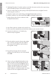
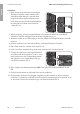
Procedure:
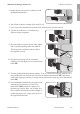
1. Unscrew the four screws of the Rapid Shutdown
Box enclosure lid using a hex socket screwdriver
(TX25) and remove the enclosure lid.
2. If the Rapid Shutdown Controller conductors are led into a separate conduit, remove the
sealing plug from one of the two enclosure openings with sealing plugs.
6 Electrical Connection
SMA Solar Technology America LLC
Installation Manual 23RSS-US-IA-xx-13
ENGLISH