
Installation Guide
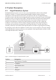


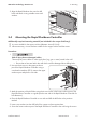

6.2 Overview of the Rapid Shutdown Box Connection
Area
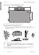
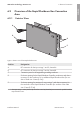
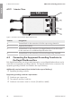
6.2.1 Exterior View
+
+
+
+
A
D
E
B
C
Figure 6: Exterior view of the Rapid Shutdown Box
Position Designation
A DC connection for the input strings 1 and 2, channel A
B DC connection for the input strings 3 and 4, channel B
C Connection point for the equipment grounding conductor
D Enclosure opening for the Rapid Shutdown Controller conductors and where
necessary for the conductors of an additional Rapid Shutdown Box (for con-
duits of trade size 16mm (0.5in))
E Enclosure opening for maximum 2 output strings* and where necessary for
the conductors of the Rapid Shutdown Controller (for conduits of the trade
size 21mm (0.75in))
* The input strings 1 and 2 (channel A) as well as 3 and 4 (channel B) are connected in parallel inside the
Rapid Shutdown Box.
6 Electrical Connection
SMA Solar Technology America LLC
Installation Manual 19RSS-US-IA-xx-13
ENGLISH