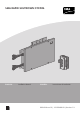
SMA RAPID SHUTDOWN SYSTEM ENGLISH Installation Manual ESPAÑOL Instrucciones de instalación RSS-US-IA-xx-13 | 101996-00.02 | Version 1.
Legal Provisions SMA Solar Technology America LLC ENGLISH Legal Provisions Copyright © 2016 SMA Solar Technology America LLC. All rights reserved. No part of this document may be reproduced, stored in a retrieval system, or transmitted, in any form or by any means, be it electronic, mechanical, photographic, magnetic or otherwise, without the prior written permission of SMA Solar Technology America LLC. Neither SMA Solar Technology America LLC nor SMA Solar Technology Canada Inc.
Important Safety Instructions ENGLISH SMA Solar Technology America LLC Important Safety Instructions SAVE THESE INSTRUCTIONS This manual contains important instructions for the following products: • RSB-2S-US-10 (SMA Rapid Shutdown Box) • RSC-1X-US-10 (SMA Rapid Shutdown Controller) This manual must be followed when using this product.
General Warnings SMA Solar Technology America LLC ENGLISH General Warnings All electrical installations must be carried out in accordance with the local electrical standards and the National Electrical Code® ANSI/NFPA 70 or the Canadian Electrical Code® CSA C22.1.
Table of Contents Table of Contents 1 2 Information on this Document................................................. 7 1.1 1.2 1.3 1.4 Validity ............................................................................................... Target group ...................................................................................... Symbols.............................................................................................. Nomenclature ..................................................
Table of Contents ENGLISH 9 SMA Solar Technology America LLC Operating the Rapid Shutdown Controller............................ 36 9.1 9.2 Triggering the Rapid Shutdown Function ......................................... 36 Resetting the Rapid Shutdown Function ........................................... 36 10 Decommissioning the Rapid Shutdown System .................... 37 11 Technical Data .......................................................................... 40 11.1 Rapid Shutdown Box.........
ENGLISH 1 Information on this Document SMA Solar Technology America LLC 1 Information on this Document 1.1 Validity This document is valid for the following device types: • RSB-2S-US-10 (SMA Rapid Shutdown Box) • RSC-1X-US-10 (SMA Rapid Shutdown Controller) 1.2 Target group The tasks described in this document must only be performed by qualified persons.
2 Safety SMA Solar Technology America LLC ENGLISH 2 Safety 2.1 Intended Use The Rapid Shutdown System consists of one or more Rapid Shutdown Boxes and one Rapid Shutdown Controller. PV systems equipped with the Rapid Shutdown System satisfy the requirements of the National Electrical Code® 2014 (Section 690.12). The Rapid Shutdown Controller activates and deactivates the Rapid Shutdown System and signals the status of the Rapid Shutdown System via the green and red LEDs.
2.2 Safety Information This section contains safety information that must be observed at all times when working on or with the product. To prevent personal injury and property damage and to ensure long-term operation of the product, read this section carefully and observe all safety information at all times. Danger to life due to high voltages of the PV array When exposed to sunlight, the PV array generates dangerous DC voltage which is present in the DC conductors.
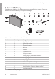
3 Scope of Delivery SMA Solar Technology America LLC ENGLISH 3 Scope of Delivery Check the scope of delivery for completeness and any externally visible damage. Contact your distributor if the scope of delivery is incomplete or damaged.
4 Product Description ENGLISH SMA Solar Technology America LLC 4 Product Description 4.1 Rapid Shutdown System The Rapid Shutdown System consists of one or more Rapid Shutdown Boxes and one Rapid Shutdown Controller. PV systems equipped with the Rapid Shutdown System satisfy the requirements of the National Electrical Code® 2014 (Section 690.12).
4 Product Description SMA Solar Technology America LLC ENGLISH Design of the Rapid Shutdown Box and Rapid Shutdown Controller Figure 3: Design of the Rapid Shutdown Box and Rapid Shutdown Controller Position Designation A DC connection for the input strings B Rapid Shutdown Box type label C Rapid Shutdown Controller type label D Rapid Shutdown Controller emergency switch E Rapid Shutdown Controller green LED F Rapid Shutdown Controller red LED 12 RSS-US-IA-xx-13 Installation Manual
5 Mounting ENGLISH SMA Solar Technology America LLC 5 Mounting 5.1 Requirements for Mounting Requirements for the mounting location: Danger to life due to fire or explosion Despite careful construction, electrical devices can cause fires. • Do not mount the Rapid Shutdown Box or Rapid Shutdown Controller in areas containing highly flammable materials or gases. • Do not mount the Rapid Shutdown Box or Rapid Shutdown Controller in areas exposed to explosion hazards.
5 Mounting SMA Solar Technology America LLC ENGLISH Dimensions for mounting the Rapid Shutdown Box: Figure 4: Position of the anchoring points of the Rapid Shutdown Box Permitted and prohibited mounting positions: ☐ The Rapid Shutdown Box and Rapid Shutdown Controller may only be mounted in a permissible position. This ensures that moisture can not penetrate the Rapid Shutdown Box or Rapid Shutdown Controller. Figure 5: Permitted and prohibited mounting positions 5.
5 Mounting ENGLISH SMA Solar Technology America LLC Risk of falling when working on the roof There is a risk of falling or slipping when working on the rooftop. Observe the applicable accident prevention regulations for work on rooftops. • Before stepping on the rooftop, ensure the load bearing capacity of all parts subjected to load. • In accordance with the accident prevention regulations, a safety harness must be worn or a safety scaffold must be used. • Use fall protection.
5 Mounting SMA Solar Technology America LLC ENGLISH 3. Attach the Rapid Shutdown Box using suitable washers and nuts. 4. Ensure that the Rapid Shutdown Box is securely attached. 5.3 Mounting the Rapid Shutdown Box with Mounting Brackets If you would like to mount the Rapid Shutdown Box on the wall or directly on the roof, proceed as described in the following. Additionally required mounting material (not included in the scope of delivery): ☐ The mounting material must be made of stainless steel.
5 Mounting ENGLISH SMA Solar Technology America LLC 5. Align the Rapid Shutdown box over the drill holes and attach it using suitable screws and washers. 5.4 Mounting the Rapid Shutdown Controller Additionally required mounting material (not included in the scope of delivery): ☐ 4 screws suitable for the support surface (diameter: 4 mm (0.16 in)) ☐ Where necessary, 4 screw anchors suitable for the support surface and the screws Procedure: 1.
6 Electrical Connection SMA Solar Technology America LLC ENGLISH 6 Electrical Connection 6.1 Safety during Electrical Connection Damage to the Rapid Shutdown Box from moisture and dust ingress. Dust and moisture ingress can damage the Rapid Shutdown Box and impair its functionality. • Do not open the Rapid Shutdown Box during rain, snow or high levels of humidity (> 95%). • Only use listed raintight or liquidtight conduit fittings to attach the conduits to the enclosure.
6.2 ENGLISH 6 Electrical Connection SMA Solar Technology America LLC Overview of the Rapid Shutdown Box Connection Area 6.2.
6 Electrical Connection ENGLISH 6.2.2 SMA Solar Technology America LLC Interior View Figure 7: Connection area inside the Rapid Shutdown Box Position Designation A Terminal block for the connection of the first output string, channel A B Equipment Ground Bar C Terminal block for the connection of the Rapid Shutdown Controller and/or for the connection of an additional Rapid Shutdown Box D Terminal block for the connection of the second output string, channel B 6.
6 Electrical Connection ENGLISH SMA Solar Technology America LLC Procedure: 1. Place a washer onto the thread. 2. Position the equipment grounding conductor horizontally below or above the thread. 3. Place the clamping bracket onto the thread and over the equipment grounding conductor. 4. Place a spring lock washer and a hex nut onto the thread and tighten the hex nut (torque: 3.5 Nm (31 in-lb)). 5.
6 Electrical Connection ENGLISH 6.4 SMA Solar Technology America LLC Connecting the Rapid Shutdown Box and Rapid Shutdown Controller Together Additionally required material (not included in the scope of delivery): ☐ Conduit: either a separate conduit (trade size: 16 mm (0.5 in) or smaller with suitable reducer bush) or use the conduit of the output strings to lay the conductors.
6 Electrical Connection Procedure: If several Rapid Shutdown Boxes are present in your Rapid Shutdown System, connect the first Rapid Shutdown Box to the Rapid Shutdown Controller first. To do so, first connect one end of the conductors to the Rapid Shutdown Box and then connect the other end of the conductors to the Rapid Shutdown Controller. • Connect the conductors to the Rapid Shutdown Box. • Connect the conductors to the Rapid Shutdown Controller.
6 Electrical Connection SMA Solar Technology America LLC ENGLISH 3. If the Rapid Shutdown Controller conductors are laid in the same conduit as the output strings, pull off the adhesive tape on the enclosure opening. 4. Insert the conduit fitting into the opening on the Rapid Shutdown Box and tighten from the inside using the counter nut. 5. Attach the conduit at the conduit fitting in the Rapid Shutdown Box enclosure. 6. Lead the conductors up to the terminal block RSC in the Rapid Shutdown Box. 7.
6 Electrical Connection ENGLISH SMA Solar Technology America LLC Connecting the conductors to the Rapid Shutdown Controller NC 1 X X 2 1 X X 2 1 + A − 2 2 1 X X 2 1 X X 2 1 RSC − B + NC 5 4 3 2 1 Figure 9: Overview of the terminal blocks in the Rapid Shutdown Controller Pin of the connecting Terminal in the terminal plate in the Rapid Shutdown Rapid Shutdown Controller Box Assignment 1 X2 Supply voltage (+12 V)* 2 2 Rapid Shutdown Controller switch 3 NC 1 Ground (0 V)
6 Electrical Connection SMA Solar Technology America LLC ENGLISH Procedure: 1. Break out the desired knockout on the Rapid Shutdown Controller using a hammer and a screwdriver When doing so, note that when using the knockouts above and below in the lower enclosure part, that the supplied adapter must be used for conduits of the trade size 16 mm (0.5 in). 2.
ENGLISH 6 Electrical Connection SMA Solar Technology America LLC 11. Damage to the Rapid Shutdown Controller due to moisture penetration Moisture ingress can damage the Rapid Shutdown Controller and impair its functionality. • Place the upper enclosure part onto the lower enclosure part and tighten the four screws using a cross-head screwdriver (PZ 2) (torque: 1.8 Nm (16 in-lb). • Ensure that the screws with a torque of 1.8 Nm (16 in-lb) are tightened. 6.
6 Electrical Connection SMA Solar Technology America LLC ENGLISH Information on laying tray cables for exposed run (TC-ER) The procedure for using conduits is described in this section. Instead of conduits, you can also use tray cables for exposed run (TC-ER). • When using tray cables for exposed run (TC-ER), select suitable cable glands and attach to the enclosure opening instead of the conduit. When doing so, ensure that the enclosure opening is sealed and no moisture can enter.
6 Electrical Connection ENGLISH SMA Solar Technology America LLC 5. Lead a silicone tube over the conductors inside the Rapid Shutdown Box. 6. Strip off the conductor insulation by 8 mm (0.31 in). 7. In the case of fine stranded wire, provide each conductor with a bootlace ferrule. 8. Connect the conductors to a five-pole plug. Observe the pin assignment. 9. Place the cable tie onto the silicone tube, tighten and cut off the projecting end of the cable tie.
6 Electrical Connection ENGLISH 6.6 SMA Solar Technology America LLC Connecting the Strings to Rapid Shutdown Box Up to four input strings and two output strings can be connected to the Rapid Shutdown Box. In the Rapid Shutdown Box, two of the four input strings are connected in parallel. The input strings must be connected to the DC conductors fitted with MC4 connectors that lead from the Rapid Shutdown Box.
6 Electrical Connection ENGLISH SMA Solar Technology America LLC 5. Lead the positive and negative conductors of the second output string up to the connecting terminal plate B. 6. Lead the existing equipment grounding conductors of the output strings to the equipment ground bar and connect them: • Strip the insulation of the equipment grounding conductor by 12 mm (0.5 in). • Thread the cylinder-head screw through the spring lock washer, the clamping bracket and the washer.
6 Electrical Connection SMA Solar Technology America LLC ENGLISH 10. Connect the conductors of the second output strings to the terminal block B. To do so, push the locking levers upwards to the stop and insert the conductors into the terminals. When doing so, ensure that the positive terminal and negative terminal have the correct polarity at the inverter. 11. Danger of pinching fingers when the terminal block locking levers snap shut The locking levers close by snapping down fast and hard.
6 Electrical Connection ENGLISH SMA Solar Technology America LLC Procedure: 1. Danger to life due to high voltages When exposed to sunlight, the PV array generates dangerous DC voltage which is present in the DC conductors. Touching the DC conductors can lead to lethal electric shocks. • Ensure that no voltage is present on the input strings. • Ensure that the Rapid Shutdown Box is closed. 2. Connect the input strings to the MC4 connectors that lead from the Rapid Shutdown Box.
7 Commissioning the Rapid Shutdown System SMA Solar Technology America LLC ENGLISH 7 Commissioning the Rapid Shutdown System 1. Commission all inverters in the system (see inverter manual). 2. Check whether the inverter to which the strings of the Rapid Shutdown Box are connected starts feed-in operation. If the inverters display no errors and start feed-in operation, the Rapid Shutdown System is connected correctly and automatically commissioned.
8 Checking the Function of the Rapid Shutdown System 8 Checking the Function of the Rapid Shutdown System The Rapid Shutdown System is supplied via the PV array. If there is insufficient irradiation on the PV array, the supply voltage of the Rapid Shutdown System is too low and the function of the Rapid Shutdown System is not able to be checked. Requirement: ☐ The Rapid Shutdown System must be commissioned. ☐ There must be sufficient irradiation on the PV array. Procedure: 1.
9 Operating the Rapid Shutdown Controller SMA Solar Technology America LLC ENGLISH 9 Operating the Rapid Shutdown Controller 9.1 Triggering the Rapid Shutdown Function • Press the emergency switch on the Rapid Shutdown Controller. ☑ The red LED on the Rapid Shutdown Controller lights briefly or flashes. The Rapid Shutdown Box reduces the voltage on the output string side. As soon as the voltage is within the permitted range, the green LED on the Rapid Shutdown Controller glows constantly.
10 Decommissioning the Rapid Shutdown System ENGLISH SMA Solar Technology America LLC 10 Decommissioning the Rapid Shutdown System Procedure: 1. Danger to life due to high voltages of the PV array When exposed to sunlight, the PV array generates dangerous DC voltage which is present in the DC conductors. Touching the DC conductors can lead to lethal electric shocks. • Switch off the DC load-break switch on the inverter. • Disconnect the DC connectors on the input strings.
10 Decommissioning the Rapid Shutdown System SMA Solar Technology America LLC ENGLISH 8. Hang the enclosure lid in the bracket of the upper enclosure edge and tighten the four screws using a hex socket screwdriver (TX 25) (torque: 6 Nm ± 0.6 Nm (53 in-lb ± 5 in-lb)). 9. Remove the equipment grounding conductor of the Rapid Shutdown Box. To do so, loosen the hexagon nut using a wrench and remove the hexagon nut, the spring lock washer and the clamping bracket from the grounding bolt. 10.
10 Decommissioning the Rapid Shutdown System ENGLISH SMA Solar Technology America LLC 15. Place the upper enclosure part onto the lower enclosure part and tighten the four screws using a cross-head screwdriver (PZ 2).
11 Technical Data SMA Solar Technology America LLC ENGLISH 11 Technical Data 11.1 Rapid Shutdown Box Maximum input voltage Input voltage range 600 V 110 V to 600 V Nominal current per channel 20 A Maximum input short-circuit current per channel 36 A Width x height x depth, without input strings sticking out of the Rapid Shutdown Box 542 mm x 340 mm x 75 mm Length x width x height of the packaging 770 mm x 395 mm x 125 mm (21.3 in x 13.4 in x 3 in) (30.3 in x 15.5 in x 4.
Enclosure degree of protection according to UL 50 Torque of the upper enclosure lid screws Installation Manual ENGLISH 11 Technical Data SMA Solar Technology America LLC 4X 1.
12 Contact SMA Solar Technology America LLC ENGLISH 12 Contact If you have technical problems with our products, please contact the SMA Service Line. We require the following information in order to provide you with the necessary assistance: • Serial number of the Rapid Shutdown Box • Serial number of the Rapid Shutdown Controller United SMA Solar Technology Toll free for USA, Canada and Puerto Rico / Llamada graStates/ Esta- America LLC tuita en EE. UU.
13 Compliance Information ENGLISH SMA Solar Technology America LLC 13 Compliance Information FCC Compliance This device complies with Part 15 of the FCC Rules. Operation is subject to the following conditions: 1. This device may not cause harmful interference, and 2. This device must accept any interference received, including interference that may cause undesired operation.
Disposiciones legales SMA Solar Technology America LLC Disposiciones legales ESPAÑOL Copyright © 2016 SMA Solar Technology America LLC. Reservados todos los derechos. Queda prohibida la reproducción total o parcial de este documento, así como su almacenamiento en un sistema de recuperación y toda transmisión electrónica, mecánica, fotográfica, magnética o de otra índole sin previa autorización por escrito de SMA Solar Technology America, LLC.
SMA Solar Technology America LLC Instrucciones de seguridad importantes Instrucciones de seguridad importantes CONSERVAR INSTRUCCIONES Estas instrucciones contienen información importante para estos productos: • RSB-2S-US-10 (SMA Rapid Shutdown Box) ESPAÑOL • RSC-1X-US-10 (SMA Rapid Shutdown Controller) Las indicaciones de estas instrucciones deben cumplirse durante el manejo con el producto.
Indicaciones generales SMA Solar Technology America LLC Observar las instrucciones de uso Lea la documentación del producto antes de trabajar con él. Siga todas las precauciones e instrucciones como se describen en la documentación. Indicaciones generales ESPAÑOL Todas las instalaciones eléctricas deben realizarse conforme a la normativa local vigente y al código National Electrical Code® ANSI/NFPA 70 o al Canadian Electrical Code® CSA C22.1.
Índice SMA Solar Technology America LLC Índice Indicaciones sobre este documento ....................................... 49 1.1 1.2 1.3 1.4 2 Área de validez ................................................................................. Grupo de destinatarios ..................................................................... Símbolos............................................................................................. Nomenclatura.............................................................
Índice SMA Solar Technology America LLC 8 Comprobación del correcto funcionamiento del Rapid Shutdown System..................................................................... 77 9 Manejo del Rapid Shutdown Controller ................................ 78 9.1 9.2 Activación de la función Rapid Shutdown....................................... 78 Restablecimiento de la función Rapid Shutdown ............................ 78 ESPAÑOL 10 Puesta fuera de servicio del Rapid Shutdown System..........
1 Indicaciones sobre este documento SMA Solar Technology America LLC 1 Indicaciones sobre este documento 1.1 Área de validez Este documento es aplicable a estos modelos: • RSB-2S-US-10 (SMA Rapid Shutdown Box) 1.
2 Seguridad SMA Solar Technology America LLC 2 Seguridad 2.1 Uso previsto ESPAÑOL El Rapid Shutdown System se compone de una o varias Rapid Shutdown Box y un Rapid Shutdown Controller. El Rapid Shutdown System cumple con los requisitos del National Electrical Code® 2014 (apartado 690.12). El Rapid Shutdown Controller sirve para activar y desactivar el Rapid Shutdown System así como para señalizar el estado del Rapid Shutdown System a través del led verde y rojo.
2 Seguridad SMA Solar Technology America LLC 2.2 Indicaciones de seguridad Peligro de muerte por altas tensiones del generador fotovoltaico Cuando recibe luz solar, el generador fotovoltaico produce una tensión de CC peligrosa que se acopla a los conductores de CC. El contacto con dichos conductores de CC puede causar descargas eléctricas mortales. • Desconecte los conectadores de enchufe de CC de los strings de entrada.
3 Contenido de la entrega SMA Solar Technology America LLC 3 Contenido de la entrega Compruebe que el contenido de la entrega esté completo y que no presente daños externos visibles. En caso de que no esté completo o presente daños, póngase en contacto con su distribuidor.
4 Descripción del producto SMA Solar Technology America LLC 4 Descripción del producto Rapid Shutdown System El Rapid Shutdown System se compone de una o varias Rapid Shutdown Box y un Rapid Shutdown Controller. El Rapid Shutdown System cumple con los requisitos del National Electrical Code® 2014 (apartado 690.12). El Rapid Shutdown Controller sirve para activar y desactivar el Rapid Shutdown System así como para señalizar el estado del Rapid Shutdown System a través del led verde y rojo.
4 Descripción del producto SMA Solar Technology America LLC Estructura de la Rapid Shutdown Box y del Rapid Shutdown Controller ESPAÑOL Figure 13: Estructura de la Rapid Shutdown Box y del Rapid Shutdown Controller Posición Denominación A Conexión de CC de los strings de entrada B Placa de características de la Rapid Shutdown Box C Placa de características del Rapid Shutdown Controller D Parada de emergencia del Rapid Shutdown Controller E Led verde del Rapid Shutdown Controller F Led rojo
5 Montaje SMA Solar Technology America LLC 5 Montaje 5.1 Requisitos para el montaje Peligro de muerte por fuego o explosión A pesar de estar cuidadosamente construidos, los equipos eléctricos pueden originar incendios. • No instale la Rapid Shutdown Box ni el Rapid Shutdown Controller en áreas en las que se encuentren materiales fácilmente inflamables o gases combustibles. • No instale la Rapid Shutdown Box ni el Rapid Shutdown Controller en áreas potencialmente explosivas.
5 Montaje SMA Solar Technology America LLC Dimensiones para el montaje de la Rapid Shutdown Box: ESPAÑOL Figure 14: Posición de los puntos de fijación de la Rapid Shutdown Box Posiciones de montaje permitidas y no permitidas: ☐ La Rapid Shutdown Box y el Rapid Shutdown Controller deben instalarse siempre en una posición autorizada para garantizar que no entre humedad. Figure 15: Posiciones de montaje permitidas y no permitidas 5.
5 Montaje SMA Solar Technology America LLC Cuando se trabaja sobre un tejado existe el riesgo de que se produzcan caídas y resbalones. Cuando vaya a trabajar en el tejado, tenga en cuenta la normativa de prevención de accidentes vigentes. • Antes de pisar el tejado, compruebe que todas las partes afectadas tienen una capacidad de carga suficiente. • De acuerdo con la normativa de prevención de accidentes deben utilizarse arneses de seguridad para las personas o andamios.
5 Montaje SMA Solar Technology America LLC 3. Fije la Rapid Shutdown Box con las arandelas y tuercas adecuadas. ESPAÑOL 4. Asegúrese de que la Rapid Shutdown Box esté bien fijada. 5.3 Montaje de la Rapid Shutdown Box con bridas de sujeción Si desea montar la Rapid Shutdown Box en la pared o directamente sobre el tejado, debe proceder según se describe a continuación.
5 Montaje SMA Solar Technology America LLC ESPAÑOL 5. Coloque la Rapid Shutdown Box en los agujeros y fíjela con los tornillos y las arandelas adecuados. 5.4 Montaje del Rapid Shutdown Controller Material de montaje adicional necesario (no incluido en el contenido de la entrega): ☐ Cuatro tornillos adecuados para la superficie (diámetro: 4 mm [0,16 in]) ☐ En su caso, cuatro tacos adecuados para la superficie y los tornillos Procedimiento: 1.
6 Conexión eléctrica SMA Solar Technology America LLC 6 Conexión eléctrica 6.1 Seguridad en la conexión eléctrica Daños en la Rapid Shutdown Box debido a la infiltración de humedad y polvo ESPAÑOL Si penetra polvo o humedad en la Rapid Shutdown Box, esta podría resultar dañada y sus funciones podrían verse limitadas. • No abra la Rapid Shutdown Box si llueve o nieva o si la humedad del aire es elevada (> 95 %).
6 Conexión eléctrica SMA Solar Technology America LLC Vista general de las áreas de conexión de la Rapid Shutdown Box 6.2.1 Vista exterior C A ESPAÑOL 6.
6 Conexión eléctrica 6.2.2 SMA Solar Technology America LLC Vista interior ESPAÑOL Figure 17: Áreas de conexión en el interior de la Rapid Shutdown Box Posición Denominación A Caja de bornes para conectar el primer string de salida, Channel A B Barra de puesta a tierra del equipo C Caja de bornes para conectar el Rapid Shutdown Controller y/o una Rapid Shutdown Box adicional D Caja de bornes para conectar el segundo string de salida, Channel B 6.
SMA Solar Technology America LLC 6 Conexión eléctrica ESPAÑOL Procedimiento: 1. Coloque una arandela en la rosca. 2. Coloque el conductor de puesta a tierra del equipo en horizontal por debajo o por encima de la rosca. 3. Coloque la abrazadera sobre la rosca y sobre el conductor de puesta a tierra del equipo. 4. Coloque 1 arandela elástica y 1 tuerca hexagonal sobre la rosca y apriete la tuerca hexagonal (par de apriete: 3,5 Nm [31 in-lb]). 5.
6 Conexión eléctrica 6.4 SMA Solar Technology America LLC Conexión entre sí de Rapid Shutdown Box y Rapid Shutdown Controller ESPAÑOL Material adicional necesario (no incluido en el contenido de la entrega): ☐ Conducto para cables: O bien tienda un conducto para cables propio (tamaño comercial: 16 mm [0,5 in] o inferior con reductores adecuados) o tienda los conductores conjuntamente en el conducto para cables de los strings de salida.
SMA Solar Technology America LLC 6 Conexión eléctrica Requisito: ☐ Todas las instalaciones eléctricas deben realizarse conforme a la normativa local vigente y al código National Electrical Code® ANSI/NFPA 70 o al Canadian Electrical Code® CSA C22.1. Procedimiento: ESPAÑOL Si su Rapid Shutdown System dispone de varias Rapid Shutdown Box, conecte solamente la primera Rapid Shutdown Box con el Rapid Shutdown Controller.
6 Conexión eléctrica SMA Solar Technology America LLC Procedimiento: 1. Suelte los cuatro tornillos de la tapa de la carcasa de la Rapid Shutdown Box con un destornillador hexagonal (TX 25) y retire la tapa. ESPAÑOL 2. Si los conductores del Rapid Shutdown Controller están tendidos en un conducto para cables propio, retire el sellador de una de las dos aberturas en la carcasa con selladores. 3.
6 Conexión eléctrica SMA Solar Technology America LLC 12. Introduzca el conector de cinco polos con los conductores conectados en la fila inferior de patillas de la caja de bornes RSC. ESPAÑOL 13. Si el sistema solo dispone de una Rapid Shutdown Box, introduzca el conector de cinco polos en la fila superior de patillas de la caja de bornes RSC y coloque una ligadura de alambre entre las patillas 3 y 4.
6 Conexión eléctrica SMA Solar Technology America LLC Indicación para el tendido de Tray Cables for exposed run (TC-ER) ESPAÑOL En este capítulo se describe si se utilizan conductos para cables. En lugar de conductos para cables también pueden usarse Tray Cable for exposed run (TC-ER). • Si utiliza Tray Cables for exposed run (TC-ER), seleccione racores atornillados para cables adecuados y colóquelos en la abertura en la carcasa en lugar de los conductos para cables.
6 Conexión eléctrica SMA Solar Technology America LLC 11. Daños en el Rapid Shutdown Controller por penetración de humedad ESPAÑOL Si penetra humedad en la Rapid Shutdown Controller, éste podría resultar dañado y sus funciones podrían verse limitadas. • Coloque la parte superior de la carcasa encima de la parte inferior de la carcasa y apriete los cuatro tornillos con un destornillador de estrella Pozidriv PZ 2 (par de apriete: 1,8 Nm (16 in-lb).
6 Conexión eléctrica SMA Solar Technology America LLC ☐ Longitud máxima de los conductores entre la primera Rapid Shutdown Box y la última Rapid Shutdown Box: 100 m (328 ft) Indicación para el tendido de Tray Cables for exposed run (TC-ER) ESPAÑOL En este capítulo se describe si se utilizan conductos para cables. En lugar de conductos para cables también pueden usarse Tray Cable for exposed run (TC-ER).
SMA Solar Technology America LLC 6 Conexión eléctrica 5. Dentro de la Rapid Shutdown Box, cubra los conductores con un tubo de silicona. ESPAÑOL 6. Pele 8 mm (0,31 in) de los conductores. 7. En los cordones finos, remate los conductores con una virola. 8. Conecte los conductores a un conector de cinco polos. Preste atención a la asignación de patillas. 9. Coloque una abrazadera para cables alrededor del tubo de silicona, apriétela y corte el extremo sobrante.
6 Conexión eléctrica 6.6 SMA Solar Technology America LLC Conexión de los strings a la Rapid Shutdown Box ESPAÑOL Tiene la opción de conectar hasta cuatro strings de entrada y dos strings de salida a la Rapid Shutdown Box. En la Rapid Shutdown Box se conectan en paralelo dos de los cuatro strings de entrada. Los strings de entrada deben estar conectados a los conductores de CC equipados con conectadores de enchufe MC4 que sobresalen de la Rapid Shutdown Box.
SMA Solar Technology America LLC 6 Conexión eléctrica 4. Introduzca los conductores positivo y negativo del primer string de salida en la caja de bornes A. 5. Introduzca los conductores positivo y negativo del segundo string de salida en la caja de bornes B. 6. Conecte los conductores de puesta a tierra del equipo disponibles de los strings de salida a la barra de puesta a tierra del equipo: ESPAÑOL • Pele 12 mm (0,5 in) del conductor de puesta a tierra del equipo.
6 Conexión eléctrica SMA Solar Technology America LLC 10. Conecte los conductores del segundo string de salida a la caja de bornes B. Empuje hacia arriba hasta el tope las palancas de protección e introduzca los conductores en los bornes. Asegúrese de que los polos positivo y negativo estén conectados con la polaridad correcta en el inversor. ESPAÑOL 11.
6 Conexión eléctrica SMA Solar Technology America LLC Procedimiento: 1. Cuando recibe luz solar, el generador fotovoltaico produce una tensión de CC peligrosa que se acopla a los conductores de CC. El contacto con dichos conductores de CC puede causar descargas eléctricas mortales. • Asegúrese de que no haya tensión en los strings de entrada. • Asegúrese de que la Rapid Shutdown Box esté bien cerrada. 2.
7 Puesta en marcha del Rapid Shutdown System SMA Solar Technology America LLC 7 Puesta en marcha del Rapid Shutdown System 1. Ponga en marcha todos los inversores de la planta (consulte las instrucciones del inversor). 2. Compruebe si el inversor al que están conectados los strings de la Rapid Shutdown Box inicia el funcionamiento de inyección.
SMA Solar Technology America LLC 8 Comprobación del correcto funcionamiento del Rapid Shutdown System 8 Comprobación del correcto funcionamiento del Rapid Shutdown System El Rapid Shutdown System se abastece del generador fotovoltaico. Si no hay suficiente irradiación en el generador fotovoltaico, la tensión de alimentación del Rapid Shutdown System es muy baja y no será posible comprobar el correcto funcionamiento del Rapid Shutdown System.
9 Manejo del Rapid Shutdown Controller SMA Solar Technology America LLC 9 Manejo del Rapid Shutdown Controller 9.1 Activación de la función Rapid Shutdown • Pulse la parada de emergencia del Rapid Shutdown Controller. ESPAÑOL ☑ El led rojo del Rapid Shutdown Controller se ilumina brevemente o parpadea. La Rapid Shutdown Box reduce la tensión en el lado de los strings de salida. Cuando la tensión se encuentra dentro del rango permitido, el led verde del Rapid Shutdown Controller permanece encendido.
SMA Solar Technology America LLC 10 Puesta fuera de servicio del Rapid Shutdown System 10 Puesta fuera de servicio del Rapid Shutdown System Procedimiento: 1. Cuando recibe luz solar, el generador fotovoltaico produce una tensión de CC peligrosa que se acopla a los conductores de CC. El contacto con dichos conductores de CC puede causar descargas eléctricas mortales. • Desconecte el interruptor-seccionador de potencia de CC del inversor.
10 Puesta fuera de servicio del Rapid Shutdown System SMA Solar Technology America LLC 8. Enganche la tapa de la carcasa en la lengüeta del borde superior de la carcasa y apriete los cuatro tornillos con un destornillador hexagonal (TX 25) (par de apriete: 6 Nm ± 0,6 Nm [53 inlb ± 5 in-lb]). ESPAÑOL 9. Retire el conductor de puesta a tierra del equipo de la Rapid Shutdown Box.
SMA Solar Technology America LLC 10 Puesta fuera de servicio del Rapid Shutdown System ESPAÑOL 15. Coloque la parte superior de la carcasa encima de la parte inferior de la carcasa y apriete los cuatro tornillos con un destornillador de estrella Pozidriv (PZ 2).
11 Datos técnicos SMA Solar Technology America LLC 11 Datos técnicos 11.
11 Datos técnicos SMA Solar Technology America LLC 4X Par de apriete de los tornillos de la parte superior de la carcasa 1,8 Nm (16 in-lb) ESPAÑOL Tipo de protección de la carcasa según UL50 Instrucciones de instalación RSS-US-IA-xx-13 83
12 Contacto SMA Solar Technology America LLC 12 Contacto Si surge algún problema técnico con nuestros productos, póngase en contacto con el Servicio Técnico de SMA. Para ayudarle de forma eficaz, necesitamos que nos facilite estos datos: • Número de serie de la Rapid Shutdown Box • Número de serie del Rapid Shutdown Controller ESPAÑOL United SMA Solar Technology Toll free for USA, Canada and Puerto Rico / Llamada graStates/ Esta- America LLC tuita en EE. UU.
SMA Solar Technology America LLC 13 Información de cumplimiento 13 Información de cumplimiento FCC Compliance 2. This device must accept any interference received, including interference that may cause undesired operation. NOTE: This equipment has been tested and found to comply with the limits for a Class B digital device, pursuant to Part 15 of the FCC Rules. These limits are designed to provide reasonable protection against harmful interference in a residential installation.
www.SMA-Solar.