
TECHNICAL NOTE - TOPIC JMTHY JMS-F: Alternative Mounting Method

Device Placement
If mounting to a bolt hole in the solar PV module frame is not possible, please choose a placement for
the JMS-F device on the solar PV module frame which avoids interfering with the solar PV mounting
system. Do not mount the JMS-F device in such way that the drain holes of solar PV modules are
blocked. Please also ensure that there is a minimum clearance of at least 38mm (1.5 inches) between
the solar PV module and the roof surface.
Device Mounting
For best results, it is generally recommended to perform the following steps before attaching the solar
PV module to the mounting system.
Alternative JMS-F Device Mounting Instructions
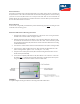
1. Orient the JMS-F device so that the JMTHY logo on the plastic cover is facing towards the
backside of the solar PV module. See Figure 1 below.
2. Slide the mounting bracket over the ange on the solar PV module frame. Ensure that the
two metal arms are not bent due to excessive force. The “teeth” on the metal arms provide
the grounding bond between the JMS-F device and the solar PV module frame according
to NEC Article 690.43.
3. Insert the M4 x 10mm machine bolt into the threaded hole on the JMS-F mounting bracket.
4. Screw the M4 x 10mm machine bolt until it is fully seated into the threaded hole on the
JMS-F mounting bracket. Tighten to 2.0 ~ 2.5 Nm (17.7 ~ 22.1 in.lb).
5. Verify electrical continuity between the JMS-F metal mounting bracket and the solar PV
module frame (recommended).
6. Connect the short (black) cable leads on the JMS-F device to the connectors on the solar
PV module prior to connecting the long (red) cable leads to another JMS-F device (series
string connection). Secure loose cables to solar PV module frame.
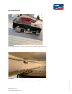
FIGURE 1
A simplied diagram showing the alternative mounting method described above