
Installation Guide

6 Electrical Connection SMA America, LLC
44 SB3-5TLUS22-IA-en-16 Installation Manual
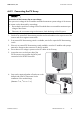
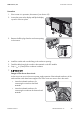
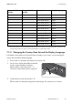
6.5 Connecting the Secure Power Supply Module
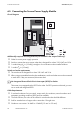
Circuit Diagram
Additionally required mounting material (not included in the scope of delivery):
☐Outlet for secure power supply operation
☐ Switch to activate the secure power outlet that is designed for at least 120 V (AC) and 10 A
☐ 1 conduit fitting (
3
⁄
4
in. (19 mm)), rain-tight or for wet locations when installed outdoors
☐ 1 conduit (
3
⁄
4
in. (19 mm))
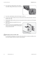
Switch and outlet requirements
☐ The switch must be designed for at least 120 V AC and 10 A.
☐ When using pre-assembled switch-outlet combinations, switch and outlet must not be connected
to each other. If they are connected, disconnect them.
Cable Requirements
☐ 5 insulated conductors for input switch, output switch, line conductor, neutral conductor and
equipment grounding conductor (EGC) must be available.
☐ To avoid confusion, the colors of the cables for switch and outlet should be different.
☐ Solid or stranded wire of copper with no more than 19 single wires
☐ Conductor cross-section: 16 AWG to 12 AWG (1.3 mm² to 3.3 mm²)
No Integrated Ground-Fault Circuit Interrupter (GFCI) for Outlet
The inverter is not equipped with a GFCI for the outlet. If a GFCI protection is desired, you must
use an outlet with integrated GFCI.