
Installation Guide

6 Electrical Connection SMA America, LLC
42 SB3-5TLUS22-IA-en-16 Installation Manual
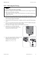
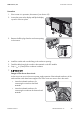
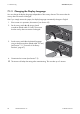
8. Connect the connection cable of the inverter in the
DC Disconnect. Use a flat-blade screwdriver (blade
width 5 mm) for this (torque 15 in-lb. (1.7 Nm)).
• Insert the red cable into the RD screw terminal
and tighten the terminal.
• Insert the orange cable into the OR screw
terminal and tighten the terminal.
• Insert the black cable into the BK screw terminal
and tighten the terminal.
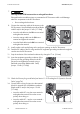
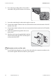
9. Install conduits with conduit fittings in the enclosure openings on the DC Disconnect.
10. Feed the DC cables of the PV strings and the DC equipment grounding conductors through the
conduits into the DC Disconnect.
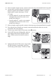
11. Strip the insulation of the insulated conductors by a length of
1
⁄
2
in. (12 mm).
12. Insert the equipment grounding conductor of the
PV array into the grounding terminal in the DC
Disconnect and tighten the terminals using a
flat-blade screwdriver (blade width: 5 mm)
(torque: 15 in-lb (1.7 Nm)).
13. Check the PV array for ground faults (see Section11.5 "Checking the PV System for Ground
Faults", page74).
14. Connect the first string for input A to the terminal
blocks for input A. Use a flat-blade screwdriver
(blade width: 5 mm) for this (torque: 15 in-lb.
(1.7 Nm)).
• Insert the cable DC+ into the screw terminal +
and tighten the terminal. Ensure the correct
polarity when doing so.
• Insert the cable DC − into the screw terminal −
and tighten the terminal. Ensure the correct
polarity when doing so.
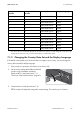
7.
Damage to the DC Disconnect due to enlarged knockouts
Enlarged knockouts enable moisture to penetrate the DC Disconnect which could damage
electronic components in the DC Disconnect.
• Do not enlarge the knockouts.